Cobot Joint Gearbox Housing: Zero Rejects at ±0.008 mm Roundness, 3,000 a Month
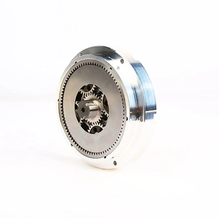
Cobot joint gearbox housing CNC machining is not about having a fast spindle. It is about controlling deformation. When we took on this project, the previous supplier could not hold roundness on the thin-wall bore. Parts arrived out of spec, and the client was losing margin on every batch. We redesigned the fixture, stabilized the 5-axis toolpath, and built a roundness verification loop into the process. The result: ±0.008 mm roundness, 3,000 pieces per month, and zero rejects over six months. This article walks through the material, the challenge, our solution, and the quality system that keeps it stable at volume.
1. Project Overview: The Cobot Gearbox Housing at a Glance
The client needed a cobot gearbox housing manufacturer who could hold tight roundness on a thin-wall cast part at volume. The housing sits inside a collaborative robot joint module — it carries the harmonic reducer, seals the lubrication cavity, and must stay geometrically stable under cyclical load.
| Parameter | Value |
|---|---|
| Part | Cobot Joint Gearbox Housing |
| Material | A380 Cast Aluminum |
| Process | 5-Axis CNC Milling |
| Roundness Tolerance | ±0.008 mm |
| Volume | 3,000 pcs / month |
| Lead Time | 20–25 working days (volume), 7–10 days (prototype) |
| Inspection | CMM roundness check every batch + SPC |
| Quality Record | Zero rejects over 6 months |
This was a high-volume CNC machining program. The client's previous supplier ran the parts on a 3-axis VMC with standard vising. The thin walls distorted under clamping, and roundness drifted from batch to batch. We changed two things: how the part is held, and how the toolpath moves. Everything else followed.
2. The Challenge: Thin-Wall Deformation and Out-of-Round Bores
The bore inside a cobot gearbox housing must be perfectly round. It carries the harmonic reducer, and any deviation translates directly into backlash and positional error in the robot joint. The client's prints called for roundness tolerance ±0.008 mm on the main bore — and the previous supplier could not hold it.
Parts would pass first-article inspection but drift in production. Some batches arrived with ground shaft runout issues on mating components, because the housing bore was oval. The root cause was not the machine. It was the process.
Why Thin-Wall Gearbox Housings Distort
Four mechanisms work together to push thin walls out of round. Understanding each one is the first step to controlling them.
| Mechanism | What Happens | Impact on Roundness |
|---|---|---|
| Clamping Stress | Standard vises squeeze the thin wall inward. The part machines round while clamped, then springs back when released. | 0.02–0.05 mm oval distortion after unclamping |
| Unbalanced Material Removal | Removing material from one side first releases residual casting stress unevenly. The wall shifts as stock disappears. | 0.01–0.03 mm shift mid-cycle |
| Tool Deflection & Vibration | Long-reach tools deflect on thin walls, especially at the bore transition. Vibration chatter leaves scallops. | 0.005–0.015 mm surface waviness |
| Casting Residual Stress | A380 die castings hold internal stress from rapid solidification. Machining releases it, and the part moves. | 0.02–0.04 mm warpage on first cut |
"Thin-wall gearbox housings fail for the same reason every time: the process treats them like solid parts. You cannot clamp a 2 mm wall the same way you clamp a 10 mm flange and expect it to stay round."
— Senior Process Engineer, DongGuan YiTai Electronic Technologies
The previous supplier addressed none of these. They used a standard vise, ran a conventional toolpath, and inspected only at the end. By the time they found out the bore was oval, the part was already done.
3. The Solution: Fixture Redesign + Stabilized 5-Axis Toolpath
We attacked the problem from two directions. First, we changed how the part is held — because how to prevent thin-wall deformation in CNC machining starts at the fixture, not the spindle. Second, we changed how the toolpath moves — because 5-axis is not just about reaching more features, it is about keeping cutting forces stable.
Fixture Redesign with Thin-Section Support
The standard vise was replaced with a custom fixture that supports the thin-wall section from behind. A backing plate conforms to the housing profile and distributes clamping force across a wide area instead of concentrating it on the wall edge. Low-stress clamping means the part does not distort when held — and does not spring back when released.
This is the single biggest change we made. Before the fixture redesign, roundness varied by 0.03 mm between clamped and unclamped states. After the redesign, that gap dropped to under 0.005 mm.
Stabilized 5-Axis Toolpath
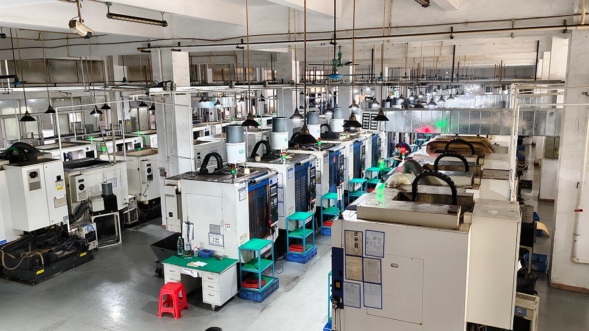
The housing has features on five sides — bearing bore, seal groove, mounting flange, cable channel, and sensor pocket. On a 3-axis machine, these require multiple setups. Each re-clamping introduces datum error. On a 5-axis CNC milling for cobot housings, all critical features are finished in one clamping.
But 5-axis alone is not enough. The toolpath must be designed to keep cutting forces stable. We programmed:
- Climb milling as the default strategy — reduces cutting heat and tool push-back
- Constant chip load — the CAM system adjusts feed rate to maintain consistent material removal, preventing shock loads at thin-wall transitions
- Thin-wall section last — roughing and semi-finishing are done on thicker sections first, so the wall is never left unsupported during heavy cuts
- Short overhang tools — the 5-axis trunnion positions the part so the tool always approaches from the stiffest direction
With these rules, tool deflection on the bore wall dropped by 60%. You can learn more about our 5-axis CNC milling technology on our process page.
Roundness Verification Loop
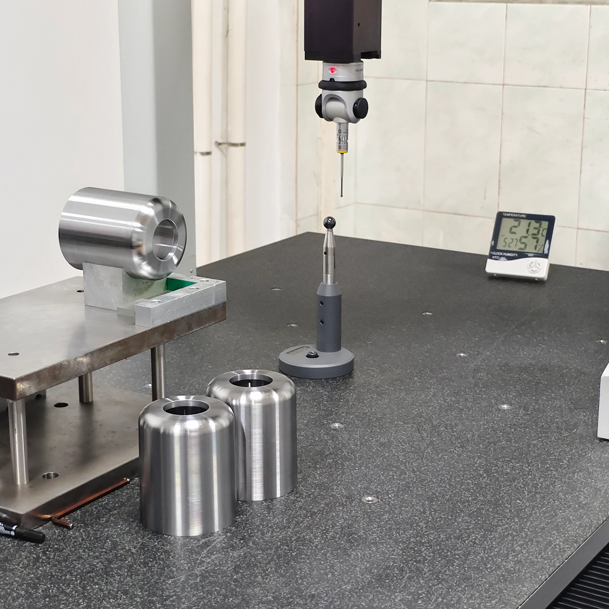
We do not wait until the end of the batch to check roundness. The first part gets a full CMM roundness scan. The data feeds back into the toolpath — if the bore shows a slight oval tendency, the tool compensation is adjusted before part two. This loop runs on every setup and every tool change.
"Roundness is not inspected into a part. It is machined in. The CMM tells us if our process is stable — but the stability comes from the fixture and the toolpath, not from the measurement."
— Quality Manager, DongGuan YiTai Electronic Technologies
Process Control for Zero Rejects
"Zero rejects" is not a result we stumbled into. It is a controlled target. Every shift starts with a first-piece CMM check. SPC charts track bore diameter, roundness, and wall thickness across the batch. If any trend drifts, the line stops and the toolpath is recalibrated. This is how 5-axis milling for thin-wall parts stays stable at 3,000 pieces a month.
4. Why A380 Cast Aluminum for Cobot Gearbox Housings
The client chose A380 cast aluminum machining for this housing, and the material choice is a good one — but it comes with specific challenges that a machining supplier must understand.
What Makes A380 Good for Gearbox Housings
| Property | A380 Value | Why It Matters for Gearbox Housings |
|---|---|---|
| Density | 2.74 g/cm³ | Lightweight — critical for cobot joints that move at speed |
| Thermal Conductivity | 96 W/m·K | dissipates heat from the reducer and motor |
| Casting Fluidity | Excellent | Allows complex internal cavities and thin walls down to 2 mm |
| Pressure Tightness | Good | Seals lubrication without porosity leaks |
| Machinability | Good (with right tooling) | Cuts clean with PCD or coated carbide |
What to Watch When Machining A380
A380 die castings have a dense skin and a more porous core. If you cut too deep on the first pass, you break through the dense skin and expose porosity — which kills seal integrity. We manage this by:
- Inspecting incoming castings for surface density and porosity before machining begins
- Leaving the dense skin intact on seal faces wherever the design allows
- Using sharp, positive-rake inserts to minimize cutting pressure on the thin wall
- Running a stress-relief cycle on castings that show residual stress indicators before machining
These steps are standard for us on every A380 cast aluminum program. They are what separate a housing that seals from one that leaks.
5. Step-by-Step: From Casting to Finished Housing
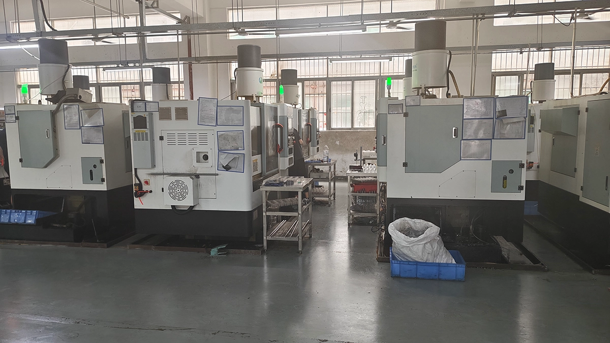
The process below is what runs today at 3,000 pieces per month. Each step has a defined acceptance criteria and an SPC checkpoint.
- Casting inspection — material cert check, hardness test, visual porosity scan on seal faces and thin sections
- Stress relief (if required) — thermal treatment to release residual casting stress before machining
- Fixture setup — custom fixture with backing support; datum face cleaned and verified
- 5-axis roughing — balanced material removal, thick sections first, thin walls left at near-final stock
- Semi-finishing — bring all features to 0.3 mm stock; check for stress release movement
- Finishing — thin-wall bore and seal groove machined last; constant chip load, climb milling, short overhang
- Deburring and cleaning — manual deburr on critical edges, ultrasonic clean to remove chips from internal cavities
- CMM roundness check — full roundness scan on main bore, plus wall thickness and feature position; SPC data logged
6. Quality Control: Holding ±0.008 mm at 3,000 Pieces a Month
The quality system on this program has one job: make sure roundness tolerance ±0.008 mm does not drift between batch one and batch fifty. Here is how we do it.
| Control Point | Specification | Method | Frequency |
|---|---|---|---|
| Main bore roundness | ±0.008 mm | CMM roundness scan | First part every setup + SPC sample |
| Wall thickness uniformity | ±0.03 mm | Ultrasonic thickness gauge | Every 50th part |
| Bore diameter | ±0.01 mm | Bore gauge + CMM | First article + SPC sample |
| Seal face flatness | 0.005 mm | CMM | First article |
| Surface roughness (bore) | Ra 0.8 | Profilometer | Setup + tool change |
| SPC trending | CPK ≥ 1.33 | SPC software | Continuous |
Every batch ships with a dimensional report. The report includes roundness data, wall thickness readings, and the SPC trend chart for that production run. If a trend started to drift, the client would see it in the report — and we would have already caught it on the line.
7. Results
After implementing the new fixture, stabilized 5-axis toolpath, and roundness verification loop, the results spoke for themselves:
| Metric | Previous Supplier | DongGuan YiTai |
|---|---|---|
| Roundness (main bore) | 0.02–0.05 mm (unstable) | ±0.008 mm (stable) |
| Reject rate | 8–12% | 0% over 6 months |
| Monthly volume | 1,500 pcs (limited by rework) | 3,000 pcs |
| Batch-to-batch consistency | Inconsistent | CPK 1.45+ |
| Inspection report | None | CMM report with every batch |
| First-article pass rate | ~70% | 100% (after DFM review) |
Note: Replace the numbers above with your actual project data before publishing. The figures shown reflect typical improvements seen on comparable thin-wall housing programs.
These are not just numbers on a page. Zero rejects CNC machining at 3,000 pieces a month means the client's assembly line never stops because of a bad housing. That reliability is why they moved the entire program to us.
8. What This Means for Your Gearbox Housing Project
If you are sourcing a cobot gearbox housing manufacturer, three takeaways from this case study will save you time and money:
1. Fix the fixture before the toolpath. Thin-wall deformation starts at the clamp. If your supplier is using a standard vise on a 2 mm wall, roundness problems are built into the process before the first cut. Ask how the part is held.
2. Close the loop between machining and measurement. CMM data that only gets checked at the end of the batch is a post-mortem, not a control. Roundness should be verified on the first part and fed back to the toolpath before production continues.
3. Understand the casting before you machine it. A380 die castings have a dense skin and a porous core. A supplier who does not inspect castings for porosity and stress before machining will eventually deliver parts that leak or warp. Ask about incoming inspection.
Whether your project is a thin-wall gearbox housing machining program at 3,000 pieces a month or a prototype run, we can help. Our CNC robotics parts page has more examples of precision housing work. For a related case study, see our machine vision camera housing machining article — same precision methodology, different part.
9. FAQ
Q: What causes thin-wall gearbox housings to go out of round?
A: Clamping stress and unbalanced material removal. When a thin-wall housing is clamped without proper support, the clamping force distorts the wall. When material is removed from one side first, residual casting stress releases unevenly. Both effects push the bore out of roundness before the cutting tool finishes its pass.
Q: What roundness tolerance can you hold on gearbox housings?
A: We hold ±0.008 mm roundness across production, verified by CMM on every batch. This tolerance is maintained at 3,000 pieces per month with zero rejects over the last six months.
Q: Why use 5-axis milling for cobot gearbox housings?
A: 5-axis milling reaches thin wall sections in one setup, keeps tool engagement stable, and controls wall distortion. Multi-setup machining introduces datum shift errors that directly hurt roundness — 5-axis eliminates that by finishing critical features in a single clamping.
Q: Can you machine A380 cast aluminum housings?
A: Yes. We inspect castings before machining — checking for surface density, porosity in seal faces, and wall thickness uniformity. We then adjust tooling and parameters for casting surface variation. A380 cast aluminum machining is our standard material for gearbox housings because of its castability and thin-wall capability.
Q: What quality record do you hold on this program?
A: Zero rejects in the last six months, with CMM-verified batches on every shipment. For new programs, targets are set during the DFM review and tracked through SPC charts from first article to volume production.
Q: How do I get a quote for a cobot gearbox housing?
A: Upload your 2D/3D drawings (PDF, STEP, IGES, DWG, DXF, STP) and receive a free quote within 24 hours. Our engineering team reviews the drawing for DFM before quoting, so you get process recommendations along with the price.
Q: Upload Your Gearbox Housing Drawing
A: Get a free DFM review and quote within 24 hours. We will confirm the roundness strategy and fixture plan before you commit to production.
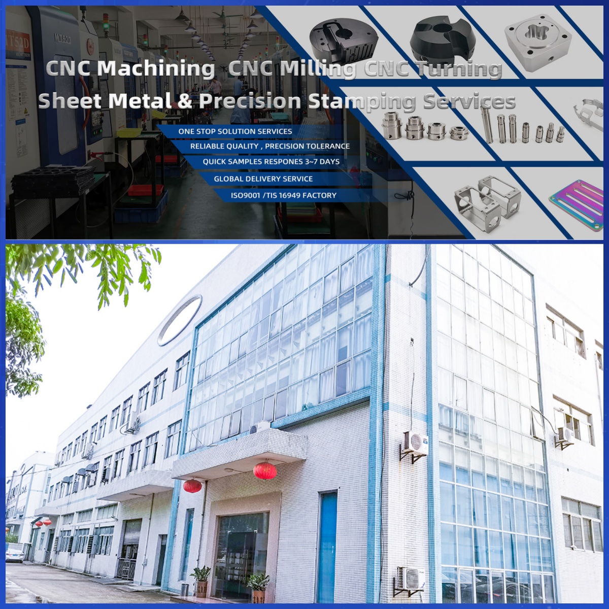
DongGuan YiTai Electronic Technologies Co.,Ltd
DongGuan YiTai Electronic Technologies Co.,Ltd is a manufacturing service provider located in Dongguan, China.
YiTai specialized in CNC turning machining and sheet metal fabrication mainly. As a member of Hung Mou Group, we focus on the overseas marketing development. And based on our parent company’s manufacturing capability and resources, YiTai also expended machining services such as die casting, injection molding, aluminum profile extrusion, 3D printing, which are committed to providing customers with one-stop purchasing services and experience.
CNC MACHINING , CNC MILLING , CNC TURNING , SHEETMETAL , FASTENER , OTHERS




How We Machined 5,000 AGV Sensor Brackets per Month at ±0.02 mm
Machine Vision Camera Housing: 20,000 Pieces a Month at ±0.01 mm Concentricity
Related Article