Bronze Valve Guides: Function, Materials, and Custom Machining
Because valve guides wear out long before the cylinder head, buyers look beyond the catalogue description. They need to know whether a supplier can consistently hold the bore dimensions and clearance.
What's in this guide
- What a bronze valve guide is?
- Materials and alternatives
- How the parts are machined?
- Critical specifications
- Installation and wear
- Sourcing custom parts
- FAQ
1. What Is a Bronze Valve Guide?
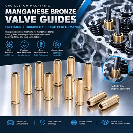
A valve guide is a short sleeve, usually a few centimetres long, pressed into the cylinder head. The valve stem moves through its bore. Bronze guides are made from copper alloys and are used when the engine specification calls for them instead of a traditional iron guide.
How a Valve Guide Keeps the Valve Aligned
The valve stem moves back and forth along the same axis each time the valve opens and closes. The guide keeps that movement on track and helps the valve head meet its seat squarely. If the stem shifts off-axis, the valve may not seat properly.
Heat Transfer, Friction, and Wear
The guide also helps carry heat from the valve stem into the cylinder head. Copper alloys generally conduct heat well, but friction and wear depend on more than the alloy: surface finish, oil supply, and operating temperature matter too.
Bronze guides are sometimes described as self-lubricating or oil-retaining. Those properties come from specific features, such as controlled porosity, graphite content, or a purpose-designed bearing surface. They don't come from the word bronze alone; a plain bronze grade won't necessarily have them.
2. Bronze Valve Guide Materials and Alternatives
Common Bronze and Copper-Alloy Options
Tin bronze, aluminium bronze, and other copper alloys are used for valve guides. Their machinability, thermal conductivity, and wear resistance vary by grade; even tin bronzes with different tin content can behave differently during machining. Specify the exact bronze valve guide material on the drawing, then match the bronze alloy machining process to that grade rather than relying on a one-size-fits-all approach.
Bronze vs Cast Iron Valve Guides
| Factor | Bronze guide | Cast-iron guide |
|---|---|---|
| Material cost | Generally higher | Generally lower |
| Thermal conductivity | Often higher, supporting heat transfer from the stem | Lower |
| Wear behaviour | Depends on grade and how it pairs with the stem | Depends on grade and the stem pairing |
| Machinability | Varies by alloy; some grades machine freely | Generally straightforward |
| Typical reason for choosing it | A specific service or performance requirement | Standard fitment in many production and repair applications |
| What decides the choice | The engine, the valve system, and the applicable service documentation | |
Specialty Copper-Alloy and Bimetal Designs
Some applications call for a specialty copper alloy or a bimetal design, such as a steel backing with a copper-alloy bore surface. These options meet specific design or operating requirements, but availability varies by supplier. Check before specifying one.
3. How the Parts Are Machined
Reviewing the Drawing and Critical Features
Start with the drawing. It should specify the bore and outside diameters, length, concentricity, straightness, bore finish, and the tolerance for each. It should also state whether the bore needs finishing after installation. Because the guide has a thin wall between two diameters, the tolerance stack affects the final geometry after press-fitting.
Preparing Bronze Bar or Tubing Blanks
Blanks can be cut from bronze bar or tubing. Tubing removes less material from the bore and can suit thin-walled guides; solid bar allows more flexibility in wall thickness and outside diameter. In either case, the setup must keep the two diameters concentric.
Deep-Hole Drilling and Bore Finishing
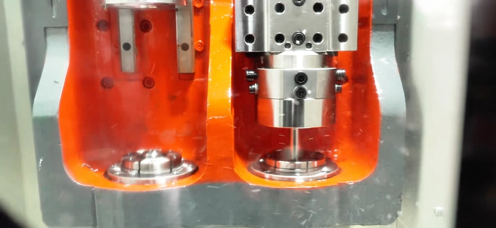
The bore is small relative to the guide's length, so it usually takes several operations to reach final size. The bore is opened in stages, brought to size by boring or reaming, then finished to meet the surface requirements. Coolant and chip removal affect whether the diameter stays consistent along the bore, so this work calls for a shop experienced in precision bore machining.
Inspecting Bore Geometry and Surface Finish
Inspection should cover the bore along its full length, not just at the ends, as well as the outside diameter, length, concentricity, straightness, and surface finish. The supplier and buyer should agree on inspection methods in advance. For tight bore tolerances, a first-article report documents the results.
Finishing the Bore After Press-Fitting
Some drawings call for the bore to be finished after the guide is pressed into the cylinder head. This is an application-specific requirement, not a general rule. Material is left in the bore so it can be brought to final size after installation, as specified by the engine or service documentation.
4. Critical Specifications for Custom Valve Guides
Bore Diameter and Valve-Stem Clearance
Valve stem to guide clearance is set by the engine, not the supplier. It depends on the valve material, running temperature, lubrication, and the applicable service documentation, so published ranges are a sanity check rather than a rule. The drawing converts that clearance into a valve guide bore tolerance: the bore is controlled, the clearance is the outcome.
Outside Diameter and Press-Fit
The outside diameter is a mating feature: its fit depends on the head bore, the head material, the installation procedure, and the drawing requirement. Because the wall is thin, an interference fit also changes the bore once installed, which is why a drawing may ask for the final bore to be cut afterwards.
Surface Finish, Concentricity, and Straightness
These characteristics matter for assembly and for keeping the valve on its axis. Bore finish affects how the stem runs and how the guide wears, concentricity keeps wall thickness even, and straightness keeps the stem on one axis. The drawing values are requirements for a specific part.
Example Drawing Specifications
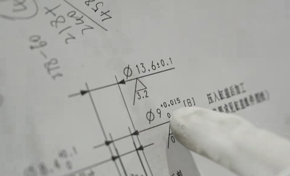
One customer drawing, shown for format only. It is not a standard.
| Feature | Example value |
|---|---|
| Bore diameter | Ø9 mm, 0 to +0.015 mm |
| Bore surface finish | Ra 3.2 |
| Outside diameter | Ø13.6 ±0.1 mm |
| Drawing note | Finish bore after press-fitting |
These values describe one part. A drawing bore tolerance, which a specific part must meet, is a different statement from the observation that a bronze guide bore can be held to about one-hundredth of a millimetre, which describes process capability. The drawing or inspection record is the source for any published figure.
5. Installation and Valve-Guide Wear
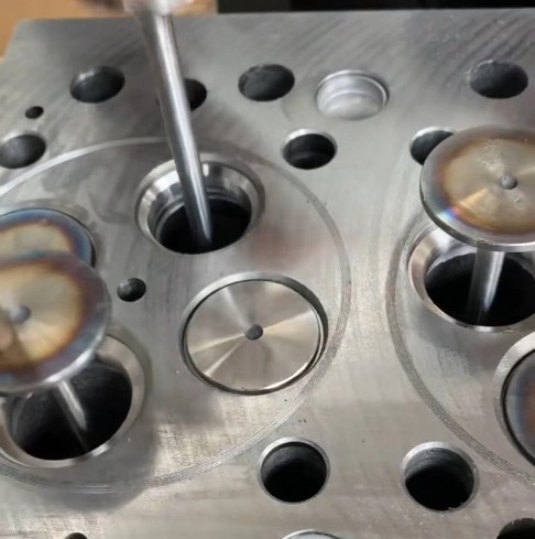
Press-Fit Installation into the Cylinder Head
The guide must be pressed in with the correct force and alignment. Heating the cylinder head or chilling the guide should be done only when the engine's service procedure specifies it. The installed alignment determines the path the valve stem follows.
Reaming After Installation
If the drawing or service procedure calls for it, the bore is reamed after installation to achieve the specified diameter and clearance. In that case, the guide is supplied with extra material in the bore for final sizing.
Possible Signs of Guide Wear
Excessive valve movement, oil-control problems, or a bore outside the drawing specification may indicate guide wear. These signs can have other causes, so inspection is needed to confirm the problem.
Replacing a Worn Guide
Replacement involves removing the old guide, preparing the cylinder-head bore, then installing and finishing the new guide. The steps vary by engine; follow the manufacturer's service instructions.
6. Sourcing Custom Bronze Valve Guides
What to Include in an RFQ
- The part drawing and revision number
- The specified bronze alloy, or required material properties if the grade is still open
- Engine and application details, including relevant service requirements
- Bore and outside diameters, length, and critical geometric tolerances
- Surface-finish requirements and any note about machining after installation
- Order quantity, inspection requirements, and required records
What to Confirm with a Supplier
Before production, confirm how the supplier will verify and document the alloy, inspect critical dimensions, approve samples, and demonstrate production capability.
For custom valve guides, send the drawing and application requirements for review before requesting a quote. The material grade, critical tolerances, and any post-installation machining requirement can all affect the process and price.
Request a Drawing Review or Quote
Submit your drawing and application details for a review of the part and its manufacturing requirements.
"The drawings that go smoothly name the alloy, give a bore tolerance, and say whether the bore is finished in place."
— Engineering review team, DongGuan YiTai
7. Frequently Asked Questions
Q: What are bronze valve guides made from?
A: Usually a copper alloy such as tin bronze or aluminium bronze. Machinability and wear behaviour differ between grades, so specify the alloy by grade.
Q: Are bronze valve guides better than cast-iron guides?
A: Neither is universally better. Cast-iron guides are standard fitment in many engines; bronze is chosen where the engine specification calls for a copper alloy.
Q: What bore tolerance should a bronze valve guide have?
A: It depends on the engine and the clearance the valve system needs. The tolerance comes from the drawing or the engine service specification, not from a general figure.
Q:Does a valve guide need to be reamed after installation?
A: Only when the drawing or service procedure calls for it. Where it does, the guide is supplied with material left in the bore so the final dimension is cut with it in place.
Q: Is valve stem to guide clearance the same for every engine?
A: No. Clearance depends on the valve material, running temperature, lubrication, and the engine maker's specification. Values for one engine should not be transferred to another.
Q: What information is needed for a custom valve guide quote?
A: The drawing and revision, the bronze grade, engine and application details, the critical bore and outside diameter tolerances, surface finish, any post-installation machining note, and your order quantity.
Conclusion
Bronze valve guides sit where a very simple geometry meets a set of numbers that all have to be right: the alloy, the bore, the wall, the alignment, and the clearance the engine needs.
The sequence is short. Confirm the material grade. Put the bore tolerance and the post-installation note on the drawing. Agree what will be inspected. Approve a sample before the run, then request a custom valve guide quote with the drawing attached.

DongGuan YiTai Electronic Technologies Co.,Ltd
DongGuan YiTai Electronic Technologies Co.,Ltd is a manufacturing service provider located in Dongguan, China.
YiTai specialized in CNC turning machining and sheet metal fabrication mainly. As a member of Hung Mou Group, we focus on the overseas marketing development. And based on our parent company’s manufacturing capability and resources, YiTai also expended machining services such as die casting, injection molding, aluminum profile extrusion, 3D printing, which are committed to providing customers with one-stop purchasing services and experience.
CNC MACHINING , CNC MILLING , CNC TURNING , SHEETMETAL , FASTENER , OTHERS



Brass Threaded Insert Kit: Sizes, Uses, and Selection
Related Article