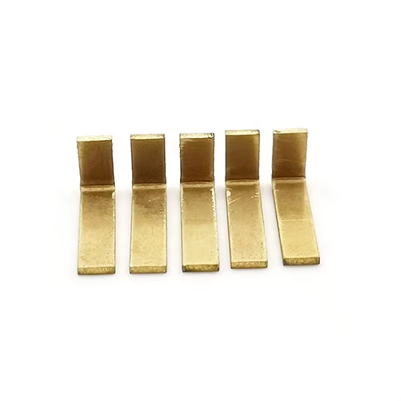
Metal Injection Molding (MIM) Process Introduction
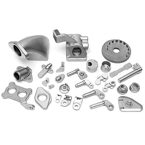
Table of Contents
1. Overview
Metal Injection Molding (MIM) is an advanced manufacturing process that combines the design flexibility of plastic injection molding with the advantages of powder metallurgy for the high-volume production of complex-shaped, high-precision, and high-performance metal parts. It is often considered a subset of "Powder Injection Molding" (PIM), specifically focusing on metal powders.
2. Core Principle
The core idea of MIM is to mix fine metal powder with a specialized binder (typically a mixture of thermoplastics and waxes) to create a homogeneous, free-flowing "feedstock." This feedstock can be injected into a mold cavity when heated, similar to plastic, forming a "green part" upon cooling. Subsequent specific processes (primarily debinding and sintering) remove the binder and densify the metal powder particles, ultimately yielding a metal part with near or full density.
MIM = Powder Metallurgy + Injection Molding. MIM is a typical interdisciplinary product, merging two distinct processing technologies. It allows engineers to overcome traditional constraints, obtaining low-cost, complex-shaped parts from stainless steel, nickel, iron, copper, titanium, and other metals using a method akin to plastic injection molding, thus offering greater design freedom than many other manufacturing processes.
3. Detailed MIM Process Steps
3.1. Feedstock Preparation
-
Metal Powder: Very fine, spherical metal powders (typically 5-25 microns in diameter) are used. A wide range of materials is applicable, including stainless steels (316L, 17-4PH, 304L, etc.), low-alloy steels, tool steels, tungsten alloys, titanium alloys, copper alloys, and cemented carbides.
-
Binder: Composed of multiple components (e.g., polypropylene, polyethylene, paraffin wax, stearic acid). Its functions are to coat the powder particles and provide flowability during mixing and injection, and to be effectively removed during debinding while providing sufficient strength to the green part to maintain its shape.
-
Mixing: Precisely proportioned metal powder and binder are heated and mixed in specialized equipment (e.g., kneaders, twin-screw extruders) to form a uniform feedstock with good rheological properties. The feedstock is typically pelletized for easier injection. After cooling, these pellets are ready for injection into the mold cavity.
3.2. Injection Molding
-
Feedstock pellets are loaded into a MIM-specific injection molding machine.
-
The feedstock is heated into a molten, viscous fluid.
-
Under high pressure (usually much higher than plastic injection molding), the molten feedstock is rapidly injected into a closed mold cavity.
-
The feedstock cools and solidifies within the mold, forming a "green part" with the final part geometry.
-
Characteristic: Capable of efficiently and mass-producing complex geometries (such as thin walls, fine features, threads, undercuts, irregular holes, etc.) that are difficult or impossible to achieve with traditional machining or powder pressing.
3.3. Debinding
This is a critical and time-consuming step in the MIM process. The purpose is to remove the majority of the binder (typically 30-50% by volume) from the green part, leaving behind a "brown part" consisting of metal powder particles with sufficient strength to maintain its shape. Common methods include:
-
Solvent Debinding: Immersing the green part in a specific solvent (e.g., trichloroethylene, heptane) to dissolve soluble binder components.
-
Catalytic Debinding: Using acid vapor (e.g., nitric acid) to catalytically decompose specific binder components (e.g., polyacetal resin).
-
Thermal Debinding: Heating slowly in a controlled atmosphere (e.g., nitrogen, hydrogen, vacuum) to melt, evaporate, or decompose the different binder components sequentially. A very slow heating rate is crucial to avoid defects.
-
Combined methods are often used in practice (e.g., solvent debinding first to remove most soluble components, followed by thermal debinding for the remainder).
3.4. Sintering
-
The debinded brown part is placed into a high-temperature sintering furnace.
-
Under a precisely controlled atmosphere (e.g., hydrogen, dissociated ammonia, vacuum, argon) and protective conditions, the part is heated to a temperature close to its metal melting point (typically 70%-90% of the base metal's melting point) and held for a specific time.
-
At high temperatures, diffusion, bonding, and densification occur between the metal powder particles, significantly reducing or eliminating porosity.
-
Result: The part undergoes significant linear shrinkage (typically 15%-20%, but with good isotropy), density increases substantially (usually reaching 95%-99%+ of theoretical density), and mechanical properties (strength, hardness, toughness, etc.) and metallurgical characteristics comparable to wrought or cast materials are achieved.
3.5. Secondary Operations (Post-Processing)
Depending on specific application requirements, sintered parts may undergo additional treatments:
-
Sizing/Coining: Applying pressure through a die to improve dimensional accuracy or local density.
-
Heat Treatment: Quenching, tempering, age hardening, etc., to obtain desired mechanical properties.
-
Surface Treatment: Plating (nickel, chromium, gold, etc.), passivation, sandblasting, polishing, PVD/CVD coating, etc., to improve corrosion resistance, wear resistance, aesthetics, or specific functions.
-
Machining: Minor secondary processing for features that cannot be directly formed (e.g., very tight internal dimensions or threads).
4. Main Advantages of MIM
-
High Geometric Complexity: Capable of producing 3D complex shapes, thin walls (as low as 0.3-0.5mm), fine features, internal holes, external threads, undercuts, etc., as integrated parts, significantly reducing assembly part counts.
-
High Material Utilization: Near-net shape, minimal material waste (<5%), far superior to machining (which can be >50%).
-
Excellent Mechanical Properties: Sintered parts achieve near-full density, with properties comparable to forgings or machined parts.
-
High Dimensional Accuracy and Good Consistency: Typical dimensional tolerances are ±0.3% to ±0.5%, advantageous for small precision parts. High part-to-part consistency in high-volume production.
-
Good Surface Finish: Typical surface roughness (Ra) after sintering is 1-4 micrometers.
-
Economical for High-Volume Production: High automation leads to low per-part cost in high-volume production (typically >10,000-50,000 pieces), once tooling is developed.
-
Wide Material Selection: Applicable to numerous alloys, including refractory metals and hard alloys.
-
Isotropic Properties: Part properties are essentially uniform in all directions.
5. Limitations of MIM
-
High Initial Investment: Tooling costs are relatively high (though usually lower than die-casting molds), and equipment investment is significant.
-
Size Limitations: Primarily suitable for small to medium-sized parts (typically weighing between 0.1 grams and 250 grams, with limits on maximum projected area).
-
Material Limitations: Not all alloys are suitable; powder costs are relatively high. Sintering high-melting-point alloys is challenging.
-
Longer Process Cycle: Debinding and sintering steps are time-consuming (can take several days).
-
Requires Specialized Design Knowledge: Design must consider MIM-specific factors like shrinkage, uniform wall thickness, draft angles, etc.
-
Low Green Strength: Green parts are relatively brittle before debinding and require careful handling.
6. Typical Application Fields
MIM is widely used in numerous industries requiring small, complex, high-performance metal parts:
-
Medical Devices: Surgical instruments (forceps, scissors, scalpel handles), dental orthodontic brackets, bone drills, joint instrument components, endoscope parts, biopsy forceps, implant components.
-
Consumer Electronics: Phone/watch SIM trays, hinges, camera lens rings, connectors, heat sinks, precision gears.
-
Automotive: Turbocharger vanes, fuel injector nozzles, lock parts, seatbelt components, sensor housings, transmission components.
-
Industrial Tools: Gun drill heads, cutter holders, fixtures, precision gears, pump/valve components.
-
Firearms: Triggers, firing pins, safeties, sight components, magazine parts.
-
Aerospace: Small engine components, sensor housings, latches, connectors.
-
Hardware: Lock cores, hinges, tool accessories.
7. Wide Range of Applicable Materials
| Material System | Alloy Grade, Composition | Application Field |
|---|---|---|
| Low Alloy Steel | Fe-2Ni, Fe-8Ni | Various structural parts in automotive, machinery and other industries |
| Stainless Steel | 316L, 17-4PH, 420, 440C | Medical devices, watch parts |
| Cemented Carbide | WC-Co | Various cutters, clocks, watches |
| Ceramics | Al₂O₃, ZrO₂, SiO₂ | IT electronics, daily necessities, clocks |
| Heavy Alloy | W-Ni-Fe, W-Ni-Cu, W-Cu | Military industry, communication, daily necessities |
| Titanium Alloy | Ti, Ti-6Al-4V | Medical, military structural parts |
| Magnetic Material | Fe, NdFeB, SmCo5, Fe-Si | Various magnetic performance components |
| Tool Steel | CrMo4, M2 | Various tools |
A wide range of metal materials is suitable for MIM. In principle, any powder material that can be sintered at high temperatures can be used in the MIM process to manufacture parts, including materials that are difficult to process or have high melting points in traditional manufacturing. MIM can process materials including low-alloy steels, stainless steels, tool steels, nickel-based alloys, tungsten alloys, cemented carbides, titanium alloys, magnetic materials, Kovar alloy, and fine ceramics. Furthermore, MIM can also involve material formulation research based on user requirements, creating alloys of arbitrary compositions and forming composite materials into parts.
8. A Comparison of MIM with Other Processes
The comparison between MIM and other processes is as follows:
| Property | MIM | PM (Powder Metallurgy) | Precision Casting | Machining |
|---|---|---|---|---|
| Weight/g | 0.01-1000 | 5g-1kg | >1 | >1 |
| Tolerance/% | <0.3 | 0.1 | 0.5-1.0 | <0.1 |
| Density/% | 98-99 | 85-92 | 95-99 | 100 |
| Strength/% | >97 | 75 | >95 | 100 |
| Surface Roughness/μm | 1 | 1-5 | 5 | 0.2-4 |
| Wall Thickness/mm | 0.2-10 | >2 | >2 | >1 |
| Complexity | High | Low | Medium | High |
| Design Flexibility | High | Medium | Medium | Low |
| Production Capacity | High | High | Low | Low |
| Material Range | High | Medium | Medium | Medium |
| Cost | Medium | Low | Medium | High |
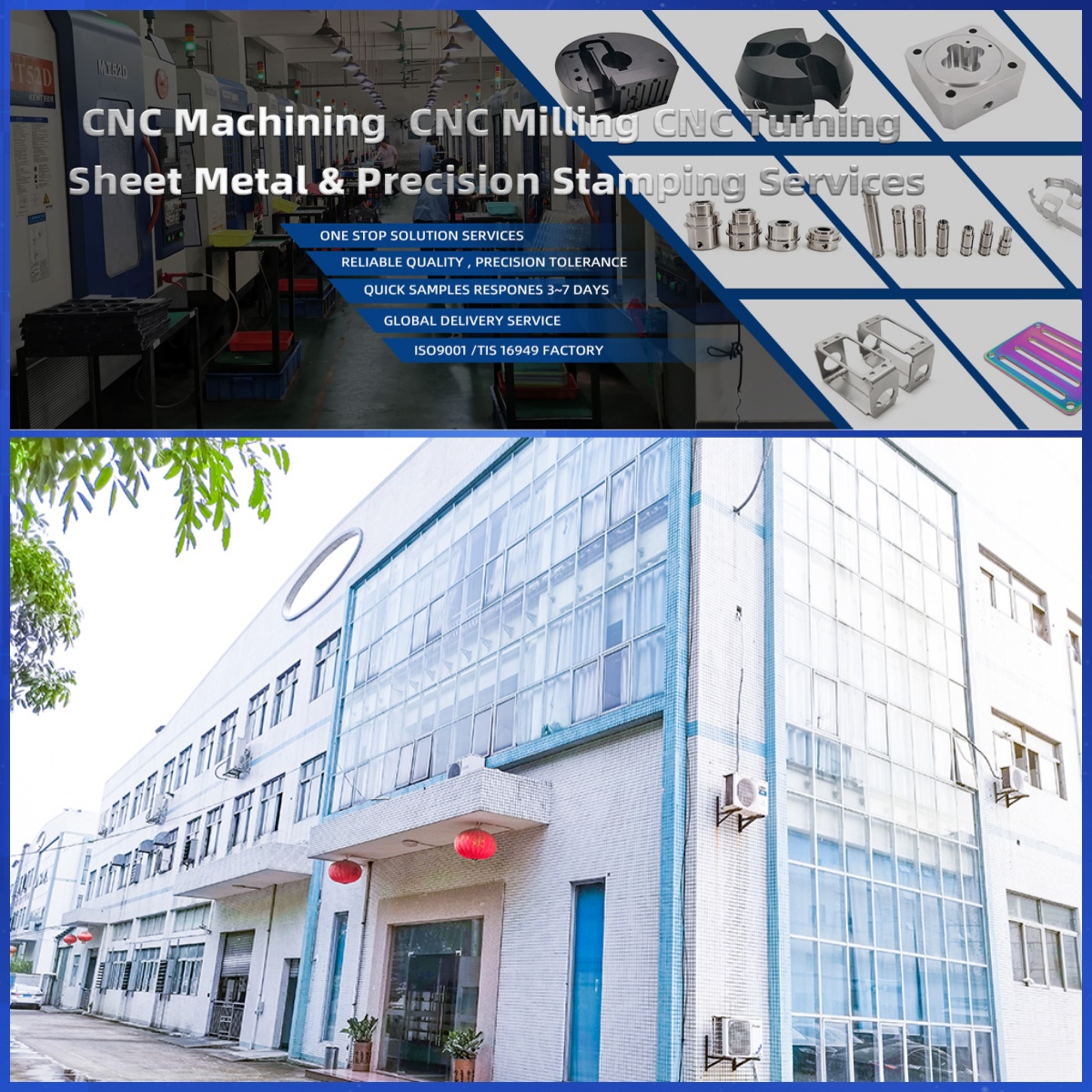
DongGuan YiTai Electronic Technologies Co.,Ltd
DongGuan YiTai Electronic Technologies Co.,Ltd is a manufacturing service provider located in Dongguan, China.
YiTai specialized in CNC turning machining and sheet metal fabrication mainly. As a member of Hung Mou Group, we focus on the overseas marketing development. And based on our parent company’s manufacturing capability and resources, YiTai also expended machining services such as die casting, injection molding, aluminum profile extrusion, 3D printing, which are committed to providing customers with one-stop purchasing services and experience.
CNC MACHINING , CNC MILLING , CNC TURNING , SHEETMETAL , FASTENER , OTHERS


The Difference Between 304, 304L, 316, and 316L – The Complete Guide!
Casting Small Aluminum Parts
Related Article