Dimensional Tolerances vs. Geometric Tolerances in CNC Machining
1. What Is the Difference Between Dimensional and Geometric Tolerances?
What Dimensional Tolerances Control
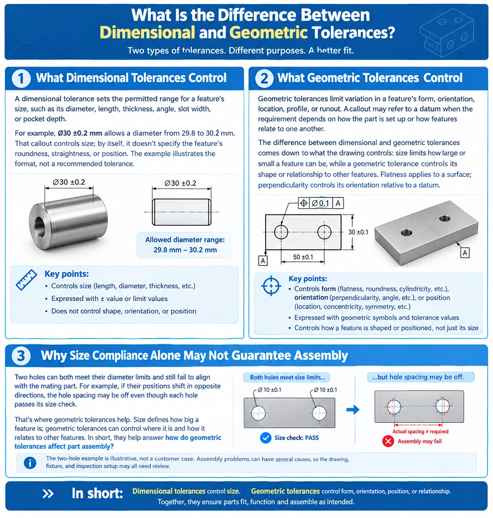
A dimensional tolerance sets the permitted range for a feature's size, such as its diameter, length, thickness, angle, slot width, or pocket depth.
For example, Ø30 ±0.2 mm allows a diameter from 29.8 to 30.2 mm. That callout controls size; by itself, it doesn't specify the feature's roundness, straightness, or position. The example illustrates the format, not a recommended tolerance.
What Geometric Tolerances Control
Geometric tolerances limit variation in a feature's form, orientation, location, profile, or runout. A callout may refer to a datum when the requirement depends on how the part is set up or how features relate to one another.
The difference between dimensional and geometric tolerances comes down to what the drawing controls: size limits how large or small a feature can be, while a geometric tolerance controls its shape or relationship to other features. Flatness applies to a surface; perpendicularity controls its orientation relative to a datum.
Why Size Compliance Alone May Not Guarantee Assembly
Two holes can both meet their diameter limits and still fail to align with the mating part. For example, if their positions shift in opposite directions, the hole spacing may be off even though each hole passes its size check.
That's where geometric tolerances help. Size defines how big a feature is; geometric tolerances can control where it is and how it relates to other features. In short, they help answer how do geometric tolerances affect part assembly?
The two-hole example is illustrative, not a customer case. Assembly problems can have several causes, so the drawing, fixture, and inspection setup may all need review.
2. Common Geometric Tolerance Groups
Form, Orientation, Location, Profile, and Runout
GD&T callouts are easier to understand by grouping them by function:
- Form: flatness, straightness, circularity, and cylindricity. These controls don't reference a datum.
- Orientation: perpendicularity, parallelism, and angularity. These controls relate a feature to a datum.
- Location: position, concentricity, and symmetry. These controls use a datum reference frame.
- Profile: line or surface profile. Depending on the callout and datum references, it can control form, orientation, and location.
- Runout: circular or total runout. These control variation as the part rotates about a datum axis.
The exact symbols and interpretation depend on the drawing's standard and edition. A symbol may not carry the same rules across different systems.
For drawings using the ISO GPS system, ISO 1101:2017 defines geometrical tolerancing symbols and interpretation rules.
Reading a Feature Control Frame
Read a feature control frame from left to right:
- The geometric characteristic symbol
- The tolerance value, including a diameter symbol when the tolerance zone is cylindrical
- Any modifier that affects the tolerance zone or its application
- Datum references, listed in precedence order
Read the full frame, including its datum references. For example, a position tolerance of Ø0.1 mm to A|B|C may constrain the feature differently from the same tolerance referenced to A|B, depending on how the datums establish the reference frame.
Which GD&T Standard Does the Drawing Use?
Drawings may follow different standards. Check that the drawing identifies the applicable standard and edition; mixing rules can lead to first-article inspection disagreements.
For drawings using the ASME system, ASME Y14.5 sets out rules for dimensioning and tolerancing, including how GD&T is stated and interpreted.
"Y14.5" is often used as shorthand for GD&T, but it refers to an ASME standard. The drawing's specified standard and edition determine which rules apply.
3. Datums and Datum Reference Frames in Machining
How Datum Features Relate to Part Function
A datum is a theoretically exact reference established from a real feature. It gives machining, inspection, and assembly a common starting point.
Choose datums that reflect how the part is located in service. If a housing rests on a mounting face and is centered by two bores, those features may be the right references. The easiest surface to clamp isn't necessarily the right datum.
For drawings based on the ISO GPS system, ISO 5459:2024 defines terminology and rules for datums and datum systems.
The 3-2-1 Setup Concept
- Three points on the primary face constrain one translation and two rotations.
- Two points on the secondary face constrain another translation and rotation.
- One point on the tertiary face constrains the final translation.
This is a fixture-planning concept for avoiding over- or under-constraint. It doesn't replace the formal GD&T datum reference frame specified on the drawing.
Aligning Machining, Inspection, and Assembly References
A part can pass machining inspection and still fail at assembly if each stage uses a different locating scheme.
Review the datum sequence and locating method before quoting. Make sure the fixture, CMM program, and assembly drawing use compatible references. A CNC drawing and DFM review is a good time to catch mismatches.
A Practical Drawing-Review Example
Consider a bracket that meets its individual dimensions, but whose mounting holes don't line up with the mating plate. A drawing review might reveal that the hole pattern was dimensioned from an edge that doesn't locate the part in assembly, and that its position callout lacks datum references tied to the mating features.
The fix would be to set the datum scheme from the assembly, add a position requirement for the hole pattern, and confirm that the fixture locates the part from the same features.
This is an illustrative scenario, not a customer case. Document the part, measurements, and process changes before presenting it as a project example.
4. How Tolerances Affect CNC Machining and Inspection
CNC machining services plan the process around the drawing requirement, so it has to be unambiguous before the first setup. The dimensional tolerances vs. geometric tolerances question is usually settled at that review, not on the shop floor.
The Relationship Between Size and Geometry
What a size tolerance covers depends on the standard. Some rules also bound form at maximum material; others need a separate form callout.
Choosing an Inspection Method for the Requirement
| Requirement | Typical method |
|---|---|
| Outside diameter, length, thickness | Micrometer, caliper, height gauge |
| Bore diameter | Bore gauge, internal micrometer, plug gauge |
| Position of a hole pattern | CMM, functional gauge |
| Flatness on a small face | Surface plate and indicator, CMM |
| Runout | Indicator setup between centres or on a mandrel |
| Profile of a surface | CMM with the model, or a dedicated gauge |
A caliper cannot verify position, and a full CMM report is more than a size check needs. Match the method to the callout, and name only equipment the shop has. See CNC part inspection and measurement.
Building an Inspection Record Around Critical Features
For each critical feature, the record should connect four things: the drawing requirement, the method used, the actual reading, and the scope of the sample.
| Critical feature | Drawing requirement | Inspection method | Actual result | Scope |
|---|---|---|---|---|
| Example: hole pattern position | Position Ø0.1 to A|B|C | CMM | [record value] | [sample / batch / date] |
This lets a buyer compare a delivered lot against the drawing without re-interpreting anything. Fill it from the inspection record, not an estimate.
5. How Tolerances Influence Custom Machining Cost
Tighter Tolerances May Require More Process Control
A tighter tolerance can change the process, not just the number on the drawing. Depending on the feature and the material, it may require:
- A different setup strategy, or more setups
- A machine with better capability
- Temperature control or in-process probing
- Additional finishing passes
- More frequent tool changes
- Higher inspection and reporting frequency
Not every reduction costs the same. Moving a bore from ±0.1 to ±0.05 mm on a lathe part differs from holding position across a large fabricated assembly.
Datum and Inspection Requirements Can Affect the Quote
Datum choice affects cost before a chip is cut. A datum that is hard to access may need a special fixture. A three-datum callout may need a CMM program a height gauge cannot replace.
Why "Tightest Possible" Is Not Always the Best Specification
A tolerance tighter than the function needs does not improve the part. It adds cost and inspection, and can push the job toward the wrong supplier.
Specify from function. A clearance hole needs position control that lets the bolt pass, not the tightest value a shop can hold. A bearing seat needs the fit the catalogue calls for, not a blanket ±0.01 mm note.
Cost Factors to Confirm Before Comparing Quotes
Compare quotes on the same drawing revision and the same quality scope. The items that move the number most:
- Material and condition
- Geometry and setups
- Critical CNC machining tolerances and GD&T callouts
- Finish and coating
- Quantity and annual demand
- Inspection and reporting
- Delivery schedule
6. Dimensional Tolerances for Linear Sizes and Fits
How Size Tolerances Define Limits and Fits
A size tolerance sets the acceptable range for a feature. A fit describes how two mating features relate, usually a hole and a shaft.
A clearance fit leaves room for movement. An interference fit holds the parts together through elastic deformation. A transition fit may result in either clearance or interference, depending on the actual sizes.
For selected linear dimensions and fits, the ISO 286 system defines standardized tolerance classes and limit deviations for holes and shafts. It covers size tolerances and fits, not geometric tolerancing rules.
Check the Drawing’s Referenced Standard and Revision
A dimension without an individual tolerance still needs a defined limit. Check the drawing notes and referenced standard: a general tolerance has a class, size range, and scope.
Applying GB/T 1804 When the Drawing References It
Some Chinese drawings cite GB/T 1804 in a general tolerance note. Apply it only when the drawing or contract calls for it, and confirm the edition, class, size range, and feature type.
For drawings that reference GB/T 1804-2000, the official standard information page lists its scope and status, but not the full text. Check the standard itself for any numerical tolerance values.
7. RFQ Checklist for Tolerance-Critical CNC Parts
What to Send With the Drawing
- 2D drawing with revision, units, datums, GD&T, and referenced standard
- 3D CAD model, where available
- Material and condition
- Critical dimensions and functional features
- Assembly or mating requirements
- Finish or post-processing
- Quantity, annual demand, and schedule
- Inspection and reporting needs
- Packaging and destination
A short note on which features are critical saves a review cycle. If forty dimensions and four decide whether the part works, name those four. That is the answer to how to choose tolerances for CNC machining.
Manufacturing Capability Information to Confirm
Ask for the capabilities that apply to your part: processes, materials, part size envelope, tolerance capability by feature, quantities, inspection methods, and delivery documentation.
Then submit a CNC machining RFQ with the drawing and the critical features marked.
8. Frequently Asked Questions
Q: What is the difference between dimensional and geometric tolerances?
A: A dimensional tolerance controls size, such as a diameter or length. A geometric tolerance controls form, orientation, location, profile, or runout relative to a datum.
Q: Can a part pass dimensional inspection and still fail assembly?
A: Yes. Every size can be within its limits while a feature is out of position, out of square, or bent. That is the gap geometric tolerances close.
Q: How do datums affect CNC machining and inspection?
A: Datums set the reference frame for machining and inspection. If the shop, the inspector, and assembly use different datums, each step can pass and the parts still will not fit.
Q: Which inspection method is used for geometric tolerances?
A: It depends on the callout. A CMM, indicator setup, functional gauge, or surface plate may be appropriate. Calipers cannot verify position or runout.
Q: Do tighter tolerances always increase machining cost?
A: No. The effect depends on the feature, material, process, and starting capability. Some reductions fit the existing process; others need a different setup or inspection plan.
Q: What should I include in an RFQ for a tolerance-critical part?
A: The drawing and revision, referenced standard, 3D model, material, critical features, mating requirements, finish, quantity, inspection needs, and delivery target.
Conclusion
Dimensional tolerances vs. geometric tolerances is not a choice between systems. Size tolerances say how big a feature can be. Geometric tolerances say how well it sits in relation to everything else.
The drawing decides how those questions are interpreted. Check the referenced standard and edition, read the full feature control frame, and confirm the datum scheme matches how the part is located. Then match the inspection method to the requirement and put the critical features in the RFQ. The step that removes the most ambiguity later is how to specify datums on an engineering drawing.
Planning a Tolerance-Critical Machined Part?
Send us your drawing, 3D model, and critical features for a manufacturing and tolerance review.
DongGuan YiTai Electronic Technologies Co.,Ltd
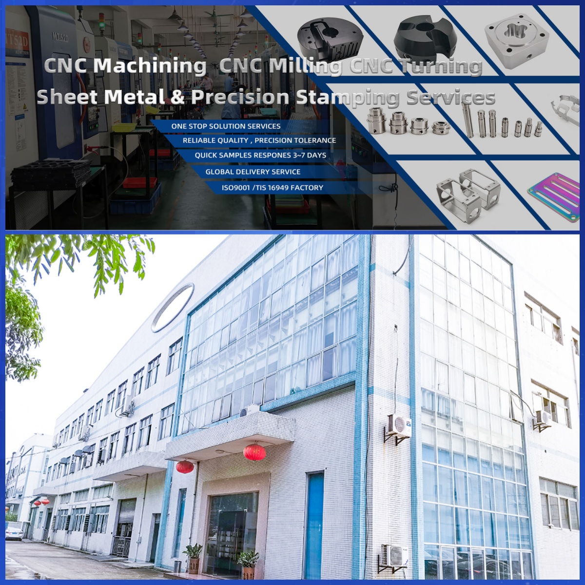
DongGuan YiTai Electronic Technologies Co.,Ltd is a manufacturing service provider located in Dongguan, China.
YiTai specialized in CNC turning machining and sheet metal fabrication mainly. As a member of Hung Mou Group, we focus on the overseas marketing development. And based on our parent company’s manufacturing capability and resources, YiTai also expended machining services such as die casting, injection molding, aluminum profile extrusion, 3D printing, which are committed to providing customers with one-stop purchasing services and experience.
CNC MACHINING , CNC MILLING , CNC TURNING , SHEETMETAL , FASTENER , OTHERS




Precision Metal Fabrication: From Drawing Review to Inspection
Metal Injection Molding vs. Plastic Injection Molding: How to Choose
Related Article