Sheet Metal Embossing: Design Rules, Tooling, and Applications
1. What Is Sheet Metal Embossing?
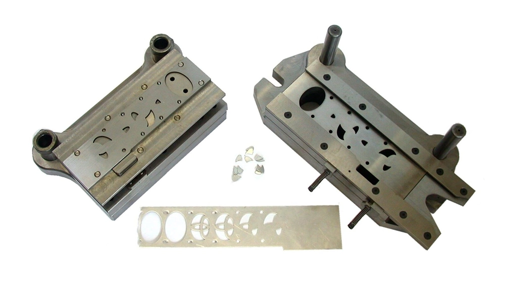
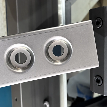
Embossing creates a raised or recessed feature through plastic deformation. The metal is not cut and not removed. It is pushed out of plane and stays there. That places it inside the wider family of sheet metal forming methods, and it follows the same logic as the rest of them: material is moved, not removed.
Common uses include:
- Locating points that position a mating part during assembly
- Mounting bosses that give a fastener a defined seat
- Stiffening ribs that add rigidity without adding a second part
- Pre-positioning features for hemming or assembly
- Sealing features that compress against a gasket or housing
- Heat-dissipation details on covers and enclosures
A note on terminology: "Embossing", "bumping", and "drawing" are used differently between shops and between CAD systems, so do not assume the word on a drawing means the same thing at the tool shop. Define the feature with a drawing and a section view before tooling starts. Deep drawing and embossing are not the same operation, so avoid calling every raised feature a deep drawn form.
2. How the Sheet Metal Embossing Process Works
How does sheet metal embossing work at the press? The answer takes under a second. The punch moves down, the metal stretches into the die cavity, and the feature is formed. The long part happens before the press runs, because everything that decides whether that stroke succeeds was fixed earlier, in the tool design. In production the feature is often formed as one station inside a wider sheet metal stamping services sequence that blanks, pierces, and bends the same part, so where the emboss sits in the die layout matters as much as its geometry.
Matched Punch and Die
An upper punch and a lower die together define the emboss shape. The punch pushes the sheet into the die cavity and the material takes the form of the gap between them. Three things control the result: the contact surfaces that press against the metal, the clearance between punch and die, and the radii at every transition. Locating features matter just as much, because a feature that forms correctly in the wrong place is still a scrapped part.
Material Flow and Local Stretching
During form, material flows toward the emboss and stretches over the punch, so wall thickness in the formed area is lower than the starting sheet. Height, corner radius, sidewall angle, and material elongation all act on that same weak point. Increase the height and strain rises. Reduce a radius and strain concentrates. Open the sidewall and the material has an easier path, but the feature loses stiffness. These variables trade against each other, so they work best when set together.
Blank Holding and Ejection
A pressure pad, spring-loaded holder, or ejector controls how the surrounding material behaves. Its job is to hold the sheet flat while the emboss forms, so the metal stretches instead of pulling the panel out of shape. On a shallow feature it may do very little. On a tall feature near a free edge it can be the difference between a clean part and a wrinkled one.
"Most emboss problems we see are decided before the die is cut. When the drawing gives a height with no transition radius and no datum to measure it from, the tool shop is guessing and the press trial becomes the design review. Put the section view on the drawing and the argument disappears."
— Engineering review team, DongGuan YiTai
3. Sheet Metal Embossing Design Guidelines
Sheet metal emboss height and radius design is where most of the risk sits. These sheet metal embossing design guidelines are screening rules, not a substitute for a forming trial on the actual material.
Emboss Height and Sheet Thickness
Emboss height should be evaluated against sheet thickness, material grade, feature width, and tooling structure together. Thickness alone does not decide what is possible, but it sets the starting point, because a thin sheet has less material to distribute into the form. We use H ≤ 5T (height no more than five times the sheet thickness) as an internal first-pass screening ratio to flag a feature as easy, borderline, or clearly demanding before anyone quotes tooling.
Scope of that ratio: H ≤ 5T is a preliminary design reference only, not an industry limit. The achievable height depends on material properties, feature geometry, tooling, and forming trials. Published shop rules of thumb differ between sources, and the real number for your part comes off a sample, not off a table.
Corner Radii and Transition Geometry
Sharp transitions are the most common reason an emboss cracks, because material has to flow around a corner and a tight corner forces that flow into a small area. Use radii that support material flow, and select them from the emboss height, sheet thickness, material, and tooling rather than from habit. Long and oblong features need extra attention at their ends, where the geometry changes fastest.
Sidewall Angle and Draft
The sidewall angle affects both material flow and how easily the part releases from the die. As a project design recommendation we work to A ≤ 45° on the sidewall for typical embossed features. Confirm how the angle is defined and measured before applying that number, because 45 degrees from the sheet plane is a very different feature from 45 degrees from the vertical. Final values should be verified against part shape and die trials.
Material Formability and Elongation
Check the material grade and temper before anything else. A 304 stainless sheet and a 6061 aluminum sheet of the same thickness will not form the same emboss, and the same alloy in a different temper behaves differently again. Evaluate forming limits and local wall thinning rather than judging feasibility by thickness alone. For demanding geometry, use forming simulation or a physical trial.
Feature Spacing and Nearby Geometry
An emboss moves material, so it affects whatever sits close to it. Review position against part edges, holes and slots, bend lines, other embosses, and welds or assembly interfaces. Distance is not the only question: the direction of the nearest feature and the amount of material between them both matter. A design review should confirm that the neighbours of an emboss will not deform, distort, or interfere with it.
4. Round vs. Oblong Emboss Features
The round vs oblong sheet metal emboss decision changes where strain lands, so it is worth settling early. A round emboss distributes deformation around a perimeter of constant curvature. An oblong emboss does not: the two ends are regions where the perimeter curves tightly, and that is where strain concentrates first. Whether an oblong feature cracks depends on the end radii, the height, the material, and the tooling.
| Feature | Design consideration |
|---|---|
| Round emboss | Typically has more uniform geometry around its perimeter, so strain is distributed more evenly |
| Oblong emboss | End regions may concentrate strain and need generous transitions |
| Stiffening bead | Performance depends on section shape, length, and orientation |
| Mounting boss | Check hole location, fastener fit, and assembly load |
5. Tooling Options for Custom Sheet Metal Embossing
Metal embossing tooling sits on a scale, and for a custom sheet metal embossing the right point on that scale depends on volume and on how settled the design is. A dedicated die makes sense when the part will not change. A simple tool makes sense when the next revision is already planned.
Dedicated Stamping Die for Production
A production die for an embossed feature usually includes a matched upper punch and lower die, guide posts or other repeatable locating features, and a pressure pad, spring-loaded holder, or ejector where the forming load requires it. It is built for one job and a defined number of strokes. Where an emboss is one feature among several, the die is developed alongside the rest of the tooling as part of custom sheet metal tooling. The work does not end at assembly: die tryout and dimensional adjustment follow, and the feature is proven by measuring formed parts.
Simple Forming Tool for Prototypes and Small Batches
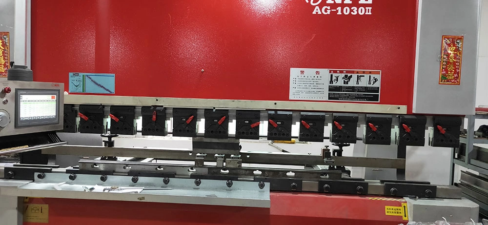
A simple forming tool is a lower-cost route for prototypes, small batches, and unusual parts. Press brake embossing for low-volume parts can work for some features, but it is not a universal method. Suitability depends on the feature shape, tool design, machine setup, and whether the workholding is safe and repeatable. Confirm feasibility with the fabricator before ordering, and do not assume a press brake tool will reproduce a high-strain feature designed for a dedicated die.
Tooling Development Sequence
We build and prove embossing tools in five steps: build the lower die cavity first, match the upper punch to the cavity, confirm locating and clamping, run a forming trial, then adjust height, radii, clearance, and material support. Working in this order keeps one variable in charge at a time.
6. Embossing for High-Volume vs. Low-Volume Production
| Factor | Dedicated stamping die | Simple forming tool |
|---|---|---|
| Typical use | Production batches | Prototypes and small batches |
| Tooling investment | Higher | Lower |
| Repeatability | Designed for repeat production | Depends on setup and operator method |
| Design changes | May require die modification | Often easier to adjust |
| Best choice | Stable design and larger volume | Early validation or limited quantities |
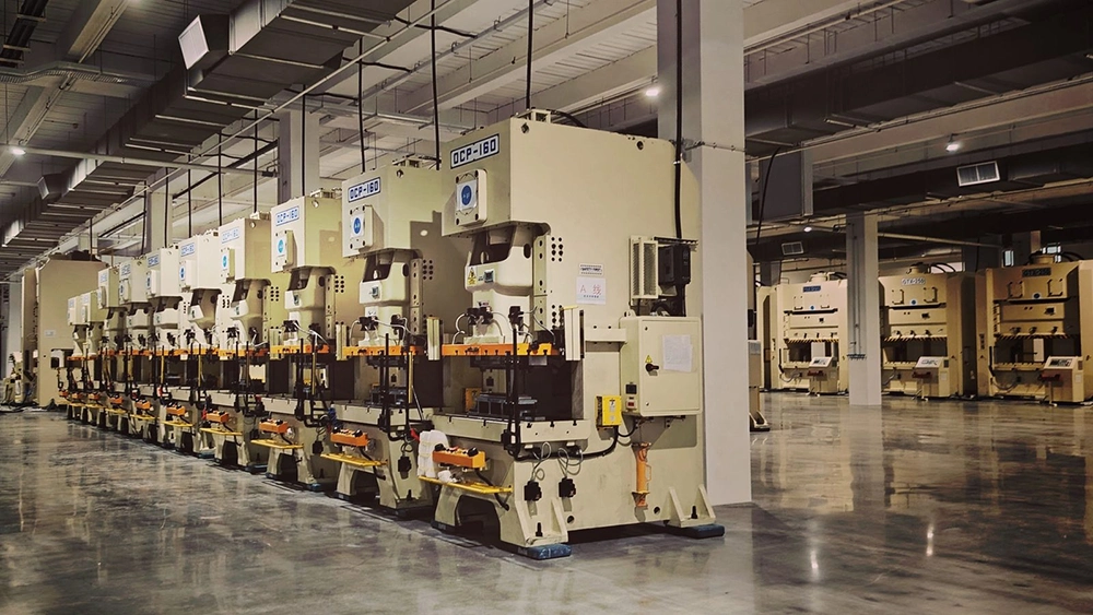
At higher volumes, sheet metal stamping can run embossing as one station in a continuous sequence, forming the feature in the same route that blanks, pierces, and bends the part. That is efficient, and it also freezes the geometry in tooling: change the height later and you are changing a die, not a program.
7. Common Embossing Defects and How to Address Them
Defects in sheet metal embossing rarely come from one cause. Height, radii, material, support, and sequence all push on the same forming limit, so a fix applied to one variable can expose a problem that was hidden behind another. Treat this table as directions to investigate.
| Defect | Possible causes | Possible actions |
|---|---|---|
| Cracking at the top or transition | Excessive height, small radii, limited material formability | Reduce height, increase radii, review material or forming stages |
| Wrinkling around the feature | Uncontrolled material flow or insufficient blank support | Review pressure pad, support, die clearance, and forming sequence |
| Insufficient height or springback | Material recovery, die geometry, or process settings | Adjust tooling after trial and inspect the formed profile |
| Distortion near thin sheet | Low stiffness or unstable support | Review workholding, tool support, and forming route |
| Cracking at oblong ends | Tight end radii or concentrated strain | Increase end radii and validate with a forming trial |
How to Prevent Cracking in Sheet Metal Embossing
Cracking starts where strain peaks and the material has the least capacity to absorb it. In practice that means the top of the form or the transition radius, and on oblong features it means the ends. Reducing height and opening the transition radius are the two fastest levers. If neither is acceptable, the next options are a more formable grade or temper, a softer sidewall angle, or forming the feature in more than one stage. Settle none of these on paper. A short trial on the real material costs less than a die that has to be recut.
How to Prevent Wrinkles During Embossing
Wrinkles come from material that has nowhere to go. When the sheet around the emboss is not held flat, the surrounding metal buckles instead of feeding into the form. Review the blank-holding approach first: pad force, pad contact area, and whether the support is stable where the feature forms. Die clearance and the forming sequence come next. Before changing the part design, confirm the tool is holding the sheet the way the forming plan assumed.
8. CAD and Drawing Considerations
Modeling the Emboss in Creo or SolidWorks
Model the intended raised or recessed geometry directly, then add the radii and sidewall transitions that production needs. A model showing a sharp-edged boss is not a forming instruction. Show a section view and specify the height from a clear datum, because "height" means nothing to the tool shop if the measurement origin is vague. Where tool design is part of the project, model the production tool separately so tool adjustments do not silently change the part.
Marking Reference Lines for Production
Some shops use laser marking to place locating or reference lines on the blank before forming. Whether this helps your part depends on the fabricator, the press setup, and the feature. Where it is used, define those lines in the engineering drawing and on a dedicated CAD layer, and agree the layer names and their meaning with the manufacturing team before the file is released. Colour conventions vary between companies, so record the convention you actually use rather than assuming a shared standard.
A sheet metal DFM review is the cheapest place to catch an emboss problem. It should check height against thickness and material, the transition radii, the sidewall angle and how it is measured, the distance to holes, edges, and bends, and the sequence the part will follow through the shop. Findings at this stage cost a drawing revision. Findings after tooling cost a die.
9. Custom Sheet Metal Embossing in Hardware Manufacturing
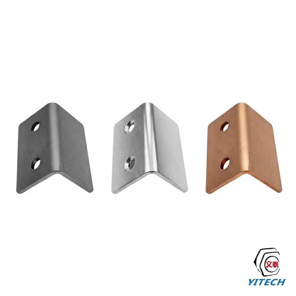
Embossed sheet metal parts rarely travel alone. In custom sheet metal fabrication they are integrated with laser cutting, punching, bending, welding, and finishing, and that combination is what makes the part useful. A bracket can be cut to its outline, embossed for stiffness, bent to shape, and finished without leaving the same production route.
For custom sheet metal embossing services, the review covers more than the feature itself. It checks the emboss dimensions against the surrounding holes, the bend order, and the assembly requirements, because a correctly formed emboss can still create a problem if the part bends after it. Non-standard or oblong features are usually worth proving with a sample before a production route is fixed.
Before You Release the Drawing
- Emboss height specified in a section view, measured from a stated datum
- Transition radii defined at every corner and at oblong ends
- Sidewall angle given with its definition and measurement direction
- Material grade and temper stated, not just thickness
- Distance to edges, holes, slots, and bend lines reviewed
- H to thickness ratio checked as a screen, not treated as a limit
- Whether the emboss forms before or after bending — confirmed with the fabricator
10. Frequently Asked Questions
Q: What is sheet metal embossing?
A: It is a forming process that creates a raised or recessed feature in sheet metal using matched tooling. The punch pushes the material into a cavity in the lower die, so the sheet stretches locally and keeps the new shape.
Q: How high can a sheet metal emboss be?
A: There is no single height limit for every material and geometry. Height must be evaluated against sheet thickness, material formability, feature width, radii, tooling, and trial results. The height to thickness ratio is a screening number, not a rule that applies to every part.
Q: How do you prevent cracking in an embossed feature?
A: Review the height, transition radii, sidewall geometry, material formability, and forming sequence. A sample trial or forming analysis may be needed for demanding features. Cracking usually comes from a stack of causes rather than one number being wrong.
Q: Why does wrinkling occur around an emboss?
A: Wrinkling can result from uncontrolled material flow, insufficient support, tooling clearance, or the forming sequence. The die and blank-holding approach should be reviewed before the feature geometry is changed.
Q: Is a press-brake forming tool suitable for embossing?
A: It may be suitable for some prototypes or low-volume parts, depending on the feature, tool design, machine setup, and safe workholding. Confirm feasibility with the fabricator before ordering tooling.
Q: What information should I provide for a custom embossing quote?
A: Provide the 2D drawing, 3D model, material and thickness, emboss dimensions, tolerance, expected quantity, nearby features, and any cosmetic or assembly requirements. The section view matters as much as the plan view.
Sheet metal embossing rewards a plain answer to a simple question: how much can this material stretch before it stops cooperating? Set the height, the radii, and the sidewall from that answer, prove it on a trial, and the feature becomes one of the least expensive ways to make a part stiffer, flatter, or easier to assemble. Send the drawing early and request a sheet metal DFM review before tooling is committed.
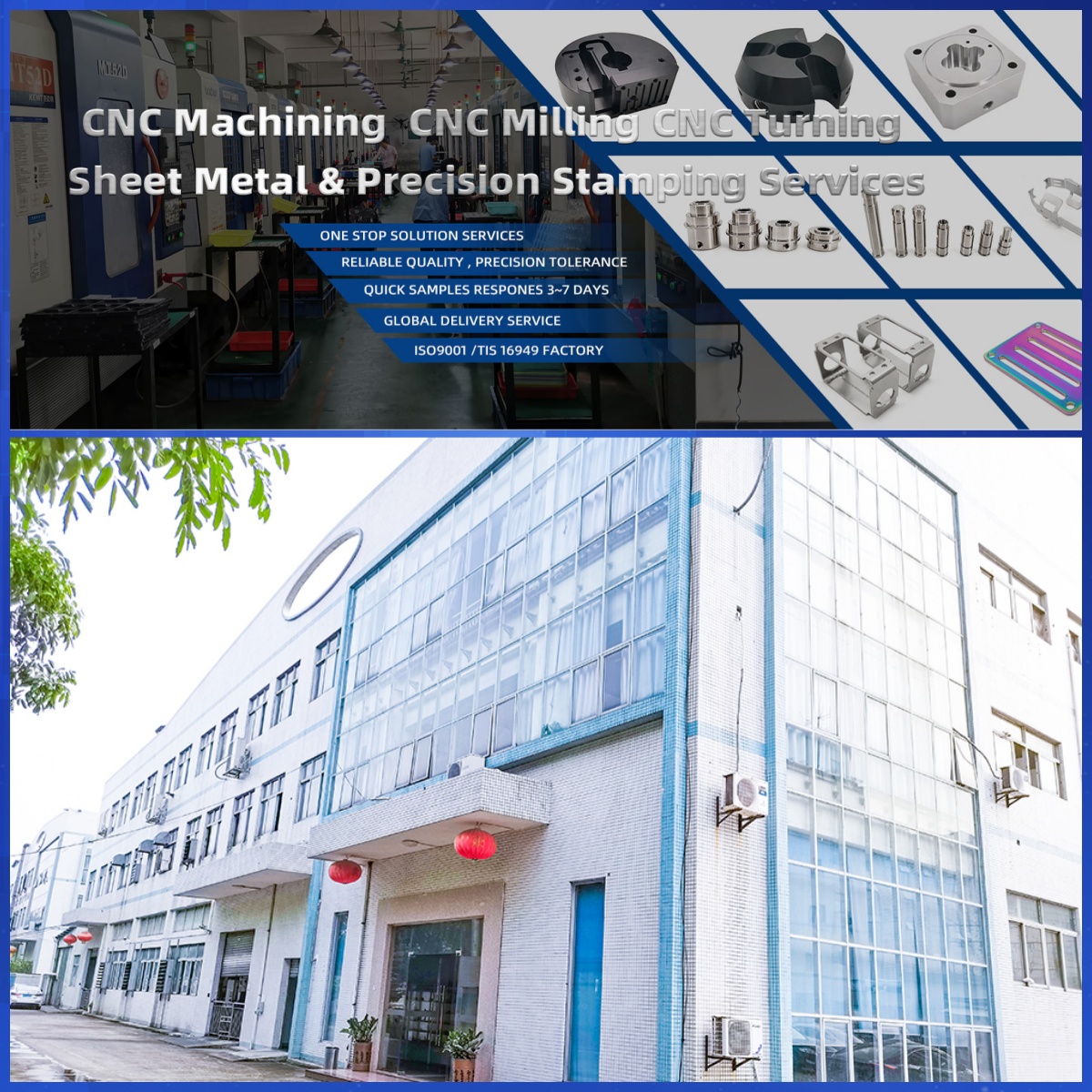
DongGuan YiTai Electronic Technologies Co.,Ltd
DongGuan YiTai Electronic Technologies Co.,Ltd is a manufacturing service provider located in Dongguan, China.
YiTai specialized in CNC turning machining and sheet metal fabrication mainly. As a member of Hung Mou Group, we focus on the overseas marketing development. And based on our parent company’s manufacturing capability and resources, YiTai also expended machining services such as die casting, injection molding, aluminum profile extrusion, 3D printing, which are committed to providing customers with one-stop purchasing services and experience.
CNC MACHINING , CNC MILLING , CNC TURNING , SHEETMETAL , FASTENER , OTHERS




Color Gradient Anodizing: Process, Design, and Cost Guide
Plastic Fabrication: Methods, Applications, and Selection Guide
Related Article