How to Control Anodizing Quality on CNC Aluminum Parts?
This guide focuses on CNC-machined parts, where even a small coating thickness can affect a bore, thread, or visible surface.
1. Define anodizing requirements before production
Many anodizing disputes start with an incomplete specification. Two parties may read "anodized" and expect different coatings. Before production, the drawing should define the following:
| Requirement | What to specify | Why it matters |
|---|---|---|
| Process type | Type II, Type III, or another class, plus the governing specification | Process types differ in thickness, hardness, and color response |
| Coating thickness | Minimum thickness or range, plus the measurement method | Affects fit, corrosion resistance, and dye depth |
| Color | Approved sample, color standard, or measured values | “Black” alone does not define an acceptable color range |
| Sealing | Whether the coating is sealed, and the test method if required | Sealing affects corrosion protection and wear resistance |
| Masking and fits | Areas to remain bare, threads, bores, and mating faces | Coating growth can affect dimensions and fit |
| Appearance | Cosmetic surfaces and the method for judging them | Clarifies whether rack marks or other marks are acceptable |
2. Control the three upstream variables
By the time a part reaches the anodizing bath, three factors have already shaped the result: the metal, the surface preparation, and the bath conditions. Dye adjustment cannot correct a problem in any of these.

Verify the alloy, temper, and material lot
Alloy chemistry affects coating color and growth. Copper-bearing grades such as 2024 may anodize toward yellow or bronze; silicon-bearing grades may appear dark gray; high-purity aluminum tends to remain brighter.
Even two lots of the same alloy, such as 6061, can produce different cosmetic results. Keep cosmetic parts from different lots separate, and confirm with the customer before mixing alloys in one load.
Keep surface preparation consistent
Cleaning, etching, desmutting, and rinsing affect how evenly the oxide forms. Oil, coolant residue, or carryover from an earlier bath may later appear as mottling or watermarks and be mistaken for a dye problem.
Document the preparation sequence and treat changes to it as process changes.
Monitor bath chemistry and process conditions
Free acid, dissolved aluminum, temperature, current density, load area, and agitation all affect the coating. Record these values for each load and document any action taken when a reading falls outside the approved window.
Published guidance provides useful reference points. The QUALANOD specifications for sulfuric acid anodizing limit free acid to 200 g/L, set dissolved aluminum at approximately 5–15 g/L, specify bath temperatures of 21°C or 20°C depending on thickness class, and set current density between 1.2 and 3.0 A/dm². These values apply to that program's architectural anodizing requirements. They illustrate a controlled process window; they are not default settings for every part.
3. Control anodizing coating thickness
Set thickness according to the application
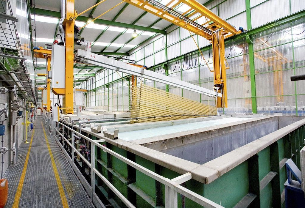
Choose thickness based on the part's function, including corrosion and abrasion requirements, desired cosmetic depth, electrical insulation, and the amount of dimensional change the fit can tolerate.
The Aluminum Anodizers Council reference guide lists conventional Type II coatings at roughly 1.8–25.4 µm and Type III coatings at 12.7–115 µm, depending on alloy and application. These ranges show how much requirements can vary.
A 25 µm coating is not a default for every part. It may exceed what a thin-wall housing or thread can accommodate, while a wear-resistant slide may require a thicker coating. Specify the target thickness, tolerance, and specification revision.
Control load, current density, and time
Current is set according to surface area, and the surface area depends on the parts on the rack—not just the traveler. A load containing a large housing and several small brackets may experience different effective current densities across the parts. A loose rack contact can also increase resistance and reduce current to parts farther along the rack.
Anodizing time and current are both controlled process variables. Keep them within a validated window for the alloy and part geometry. If a growth coefficient is used for dimensional compensation, base it on measurements from the production line using representative coupons.
Measure and record coating thickness
Eddy-current measurement is commonly used in production for thin, non-conductive coatings on aluminum. Cross-section checks can be used when results are disputed.
The inspection plan should state how many parts to check per lot, which surfaces to measure, and whether the requirement is a minimum or an average.
Benchtop XRF coating-thickness analyzer in an inspection room
A measurement is useful only when its record can be traced. Log the instrument, calibration date, measurement locations, sample size, batch, and results. Keep the specified requirement and measured value in separate fields.
4. Control anodizing color variation
Approve a color reference and acceptance method
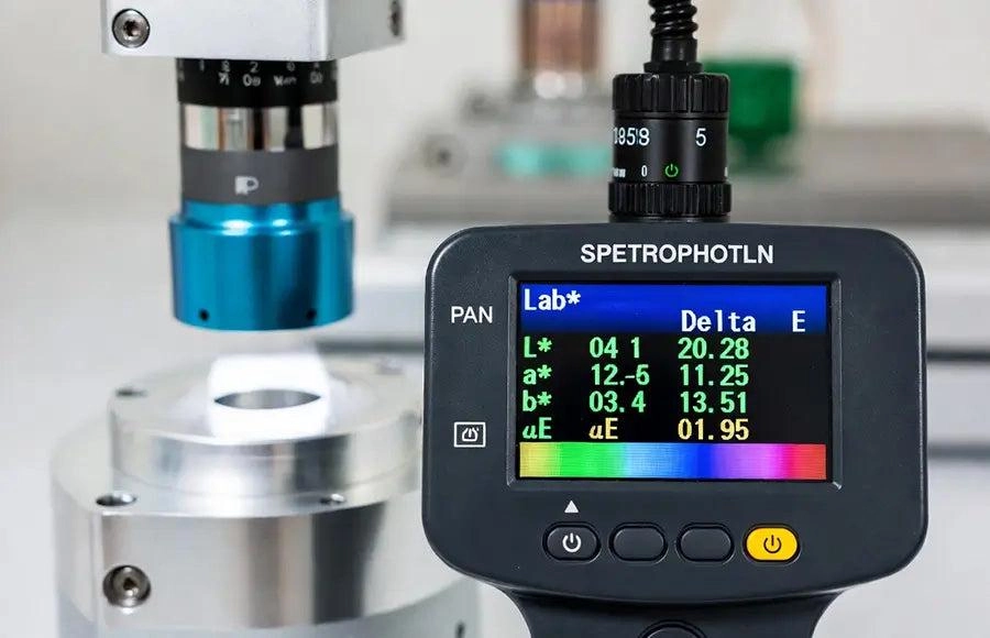
Start with a physical reference accepted by both parties: a coated coupon, a first-article part, or a standard plaque kept on file. L*, a*, b* values and a ΔE limit are commonly used to describe color, but the acceptance limit is a commercial decision. State it in the specification, tie it to the approved sample, and identify the instrument and illuminant.
Keep alloy, surface finish, dyeing, and sealing consistent
The same dye bath can produce different results on a machined surface and a bead-blasted surface, or on 6061 and 7075. Group parts by alloy and prior surface condition. Keep dye concentration, time, temperature, and sealing within defined limits; a longer or hotter seal can shift the shade.
If the color is wrong, review the process in sequence: pretreatment, coating thickness, sealing, and then the dye bath. Changing the dye to compensate for a pretreatment problem may only shift the problem elsewhere.
Use a repeatable color inspection sequence
- Confirm the approved reference sample.
- Check color on the first article before the production run.
- Inspect samples at the frequency defined in the control plan.
- Record batch release as a documented decision.
- If a result is out of limit, stop release and recheck the sample and process records.
Figure 1 — Color inspection and release sequence. The frequency and limits should come from the control plan.
The inspection sequence matters as much as the instrument. Confirm the reference, check the first article, sample at the agreed frequency, and document the batch release. Full inspection has a cost, so include it only when required by the customer or control plan. Any published color measurement should come from the supplier’s own records.
5. Use racking and part orientation to prevent process problems
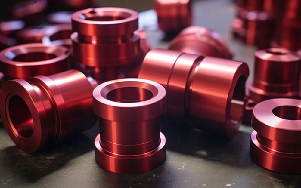
Racking connects part geometry with the anodizing process. Electrical contact must be reliable, air must escape, and solution must drain.
- Contact: Choose a rack contact point on a non-cosmetic surface and record its location. Thin walls and open frames can flex when lifted wet; support them at a second point if needed rather than tightening a single contact.
- Spacing: Parts placed too close together can shield one another. A surface that traps gas may remain pale regardless of the bath conditions.
- Pockets: A pocket needs a path for both venting and drainage. Orientation matters: a blind hole that anodizes cleanly in one position may trap air in another.
- Edges: Sharp corners concentrate current and can build coating more quickly, increasing the risk of burn marks. A chamfer may help, but its size should be determined for the part.
6. Anodizing defects: causes and corrective actions
| Defect | Possible causes to investigate | Process response |
|---|---|---|
| Uneven color or mottling | Alloy or surface variation, incomplete cleaning, bath or dye variation, inconsistent sealing | Verify material lots and pretreatment; review bath and sealing records |
| Bare or pale areas in cavities | Trapped gas, poor wetting, restricted solution exchange, rack shadowing | Review orientation, racking, spacing, and solution movement |
| Dark or burned edges | Local current concentration, part geometry, contact, process conditions | Review edge geometry, rack setup, electrical contact, and validated settings |
| Rack marks or handling scratches | Contact location, loading, transfer, packaging | Define contact areas and protect parts during handling |
| Powdery or damaged film, apparent peeling | Substrate, pretreatment, bath condition, post-treatment | Trace the process sequence and inspect the surface before identifying a root cause |
| Watermarks or haze | Inadequate rinsing, residue carryover, inconsistent draining or drying | Review rinsing, transfer, drainage, and drying |
Describe the defect before assigning a cause. "Pale matte patch on the floor of a 30 mm pocket" gives the investigation a useful starting point; "bad anodizing"does not.
Avoid settling on one cause based on appearance alone. Gas retention, poor wetting, and restricted solution exchange can look similar in a photograph. Reviewing the rack and part orientation can help distinguish them.
7. Build a Practical Anodizing Quality Control Plan
An anodizing quality control plan does not need to be long — one line per control point, with a named record.
| Control point | What to define or record |
|---|---|
| Incoming material | Alloy, temper, supplier lot, part condition |
| Pretreatment | Cleaning and surface preparation checks |
| Anodizing bath | Applicable chemistry and process window |
| Racking | Contact points, spacing, orientation, load |
| Thickness | Requirement, method, locations, sample scope |
| Color | Approved reference, method, acceptance limit, result |
| Sealing and handling | Sealing requirement, rinse, drying, packaging |
| Batch release | Inspection record, deviations, customer documents |
Where a real production case belongs, keep it factual: the problem, the adjustment, and the result on a stated sample. This article carries no factory data, so treat these as a form to fill from your records — [alloy/temper], [specified thickness], [measured results], [sample size and batch]. A number without a sample size is a rumor with units.
8. Design CNC parts for reliable anodizing
Design choices are easier to address in CAD than after a rejected production lot. For CNC-machined aluminum parts, consider the following:
- Identify post-coating dimensions. The oxide grows into and outward from the surface, changing dimensions. Mark which dimensions apply after coating and where material must be left for the anodizer.
- Choose the rack contact point deliberately. A mark on a hidden flange may be acceptable; the same mark on a visible face may not be.
- Provide vent and drain paths for pockets. A closed cavity with a narrow opening can trap gas or solution, depending on its orientation.
- Specify the finish in the RFQ. Process type, thickness, color, masking, and inspection all affect cost. Include them so the quote reflects the actual requirements.
If one supplier machines and finishes the part, these points can be addressed in a single DFM review. CNC machining and finishing planned from the same drawing can reduce handoffs and clarify requirements before production.
9. FAQ
Q: How do you control anodizing color variation?
A: Start from an approved physical sample, not a color name. Hold alloy, finish, dye and sealing inside one window, measure against that sample with an agreed method and limit, and check pretreatment before blaming the dye.
Q: How is anodizing coating thickness specified and measured?
A: Put a minimum or a range on the drawing with the type and specification. Measure by eddy current in production, confirm with a coupon or cross-section, and record instrument, locations, sample size and batch.
Q: Is 25 microns the ideal anodizing thickness for every part?
A: No. It sits at the top of the conventional sulfuric range, not at a universal optimum. Reference ranges run from about 1.8 to 25.4 microns for Type II and 12.7 to 115 microns for Type III.
Q: Type II vs Type III anodizing: what is the difference?
A: Both use sulfuric acid. Type II is the conventional protective and decorative coating, thin and easy to dye. Type III is a hard coating for wear: thicker, darker, with a larger dimensional effect.
Q: How can CNC part design reduce anodizing defects?
A: Give gas a way out and solution a way to drain, put rack contact on non-cosmetic faces, break sharp edges that concentrate current, and mark which dimensions are final after coating.
Q: What information should I include in an anodizing RFQ?
A: Alloy and temper, type and specification, thickness, color reference, sealing, masked areas, threads and fits, cosmetic criteria, quantity, and the inspection documents you expect.
Q: Request a DFM Review for Your Anodized CNC Parts
A: Send the drawing and the finish requirement — type, thickness, color, masking and inspection — and our engineers will flag the features that put the coating at risk before the first part is cut. See anodizing services for CNC parts or request a DFM review.
DongGuan YiTai Electronic Technologies Co.,Ltd
DongGuan YiTai Electronic Technologies Co.,Ltd is a manufacturing service provider located in Dongguan, China.
YiTai specialized in CNC turning machining and sheet metal fabrication mainly. As a member of Hung Mou Group, we focus on the overseas marketing development. And based on our parent company’s manufacturing capability and resources, YiTai also expended machining services such as die casting, injection molding, aluminum profile extrusion, 3D printing, which are committed to providing customers with one-stop purchasing services and experience.
CNC MACHINING , CNC MILLING , CNC TURNING , SHEETMETAL , FASTENER , OTHERS




Metal Spinning: How the Process Works and When to Use It
Related Article