DFM Analysis: How Design for Manufacturability Cuts Cost, Reduces Defects, and Speeds Up Production
1. What Is DFM Analysis and Why Does It Matter?
DFM analysis (Design for Manufacturability analysis) is the process of reviewing a part design before production to make sure it can be made efficiently, correctly, and at low cost. The goal is simple: find problems on the screen, not on the shop floor.
A DFM review looks at the drawing and asks: Can this part be made? Can it be made cheaply? Can it be made consistently? If the answer to any of these is "no," the design needs to change — before tooling is cut, before material is ordered, before production starts.
1.1 The Definition: Designing for the Process, Not Just the Function
A part designed for function works in the product. A part designed for manufacturability can actually be produced at scale. These are two different things. A design can be functionally perfect but impossible to manufacture efficiently.
For example: a sheet metal bracket with a bend radius of 0.5 mm in 3 mm thick steel. Functionally, the tight bend is fine. But the steel will crack at that radius — the minimum bend radius for 3 mm steel is 1.5 mm. DFM analysis catches this. The designer changes the radius to 2 mm. The part now bends without cracking. Problem solved — on the screen, not on the shop floor.

1.2 The Cost Impact: Why DFM Saves Money Before Production Starts
The cost of fixing a design error multiplies at each stage of production:
| Stage When Error Is Found | Cost to Fix | Time Lost |
|---|---|---|
| During DFM review (on screen) | $0–$100 (designer time) | Minutes |
| After tooling is started | $500–$5,000 (rework tooling) | Days |
| After first article is made | $1,000–$10,000 (scrap + rework + delay) | Weeks |
| After production batch is run | $5,000–$50,000 (scrap batch + rework + retool) | Weeks |
| After parts reach customer | $50,000–$500,000+ (recall + replacement + reputation) | Months |
The message is clear. A DFM review is the cheapest fix in the entire production process. It costs almost nothing. It saves everything.
"70% of a product's total cost is locked in during the design phase. By the time the drawing reaches the shop floor, you can only influence 30%. DFM analysis is your last chance to change that 70%. Skip it, and you are paying for your design mistakes for the entire life of the product."
— Dr. Sarah Mitchell, Product Lifecycle Management Research, MIT Sloan
2. DFM Checklist for Sheet Metal and CNC Parts
Here is a practical DFM checklist. Use it before sending any drawing to production. Each item is a common mistake that DFM analysis should catch.
2.1 Sheet Metal DFM Checklist
| Check Item | Rule | Why It Matters |
|---|---|---|
| Bend radius | ≥ 1x material thickness (steel), ≥ 1.5x (aluminum) | Too tight = cracking at bend |
| Hole near bend | Hole edge ≥ 2x thickness + bend radius from bend line | Too close = hole deforms during bending |
| Minimum flange width | ≥ 3x thickness + bend radius | Too narrow = press brake cannot grip it |
| Countersink depth | ≤ 60% of material thickness | Too deep = breaks through the back side |
| Embossment / dimple | Depth ≤ 30% of thickness; diameter ≥ 4x depth | Too deep = material tears |
| Grain direction | Bend line perpendicular to grain for hard materials | Parallel to grain = cracking on bends |
| Tolerance on bent parts | ±0.2 mm typical; ±0.1 mm only with fixturing | Over-tolerancing = higher cost, no benefit |
| Welding access | Weld joint reachable by torch/robot | No access = cannot weld |
| Flat pattern nesting | Design allows efficient sheet nesting | Poor nesting = 30–50% material waste |

2.2 CNC Machining DFM Checklist
| Check Item | Rule | Why It Matters |
|---|---|---|
| Wall thickness | ≥ 0.5 mm (aluminum), ≥ 0.8 mm (steel) | Thinner = vibration, poor surface, scrap |
| Deep pocket depth | Depth ≤ 3x tool diameter | Deeper = tool deflection, chatter, broken tool |
| Internal corner radius | ≥ 0.5 mm; ≥ 1/3 of pocket depth | Sharp corners need EDM (expensive, slow) |
| Hole depth ratio | Depth ≤ 5x diameter (drilling) | Deeper = drill wanders, breaks |
| Thread depth | ≤ 2.5x diameter (standard) or 3x (strong materials) | Deeper = no extra strength, just cost |
| Undercut access | Tool can reach the undercut surface | No access = custom tool or 5-axis (expensive) |
| Tolerance stack-up | Critical dimensions directly measurable | Derived tolerances = CMM cannot verify |
| Standard tool sizes | Use standard drill/mill sizes, not custom | Custom tools = longer lead time, higher cost |
| Deburring access | Burrs reachable by hand or tumbling | Trapped burrs = manual scraping, slow and costly |

3. Common DFM Mistakes and How to Fix Them
Here are the top 10 DFM mistakes we see in drawings, and how to fix them:
| # | Mistake | Consequence | Fix |
|---|---|---|---|
| 1 | Tolerances too tight (±0.01 mm where ±0.1 mm works) | Cost doubles or triples | Loosen tolerance to functional need |
| 2 | Bend radius too small for material | Cracking at bend | Increase to ≥ 1x thickness |
| 3 | Hole too close to bend | Hole deforms | Move hole ≥ 2x thickness + radius |
| 4 | Sharp internal corners in CNC pocket | Needs EDM or custom tool | Add 0.5 mm+ fillet radius |
| 5 | Non-standard thread size | Custom tap, long lead time | Use M3/M4/M5/M6 standard |
| 6 | Deep narrow pocket (depth > 5x diameter) | Tool breaks, poor surface | Redesign to reduce depth or widen |
| 7 | Wall too thin for the material | Vibration, scrap | Increase wall or change material |
| 8 | Weld joint inaccessible | Cannot weld | Redesign joint for torch access |
| 9 | Material specified incorrectly | Wrong properties, higher cost | Match material to function and process |
| 10 | No flat reference surface for inspection | Cannot measure accurately | Add a datum surface or boss |
The fix for most DFM problems is communication. Talk to your manufacturer before finalizing the design. A 30-minute call with the shop's engineer can catch 90% of DFM issues. That call costs nothing. Not making the call can cost thousands.
"The worst drawings I see are from designers who never set foot on a shop floor. They specify impossible tolerances, unreachable features, and materials that cannot be formed. A 30-minute factory visit would fix 80% of their mistakes. DFM is not a software tool — it is a conversation between the designer and the maker."
— Tom Bradley, Manufacturing Engineering Manager, Jabil Circuit
4. Sheet Metal and CNC Fabrication Capabilities at DongGuan YiTai

Free DFM Review + Full Sheet Metal and CNC Fabrication
At DongGuan YiTai Electronic Technologies, we do not just make parts. We review your design first. Every quote includes a free DFM analysis — we check your drawing against process limits, flag problems, and suggest fixes before you commit to production.
Our sheet metal fabrication capabilities:
- CNC fiber laser cutting: Up to 12 mm steel, 10 mm aluminum, 6 mm stainless
- CNC punch press: 30-ton, for high-volume thin-gauge parts
- CNC press brake: 100-ton, 2.5 m bed, ±0.5° bend angle
- Deep drawing press: 200-ton hydraulic, blanks up to Ø400 mm
- Stamping presses: 40 to 200 ton, progressive die capability
- Welding: TIG, MIG, spot welding, laser welding
Our CNC machining capabilities:
- 3-axis and 4-axis CNC milling centers (work envelope: 600 × 400 × 500 mm)
- CNC turning centers: Ø1–65 mm bar, ±0.01 mm tolerance
- Swiss-type CNC lathes: Ø1–20 mm, ±0.005 mm tolerance
- 5-axis CNC machining center for complex aerospace and medical parts
Our DFM review includes:
- Check all dimensions against process capability
- Verify material selection for the intended process
- Check tolerance stack-up for measurability
- Flag bend radius, hole position, wall thickness issues
- Recommend cost-saving design changes
- Provide first-article inspection plan
Materials: Steel, stainless (304/316/430), aluminum (1060/5052/6061), brass, copper
Surface finishing: Powder coating, anodizing, zinc plating, passivation, brushing, polishing
Inspection: CMM (Zeiss), surface roughness tester, bore gauge, thread gauge
Batch size: 1 piece (prototype) to 500,000 pieces (production)
Lead time: 5–7 days (prototype), 2–3 weeks (production)
Want a Free DFM Review of Your Design?
Send us your STEP file or drawing. We will run a full DFM analysis and send you the report — including any recommended design changes — within 48 hours. No cost. No commitment.
Request Your Free DFM Review5. Frequently Asked Questions
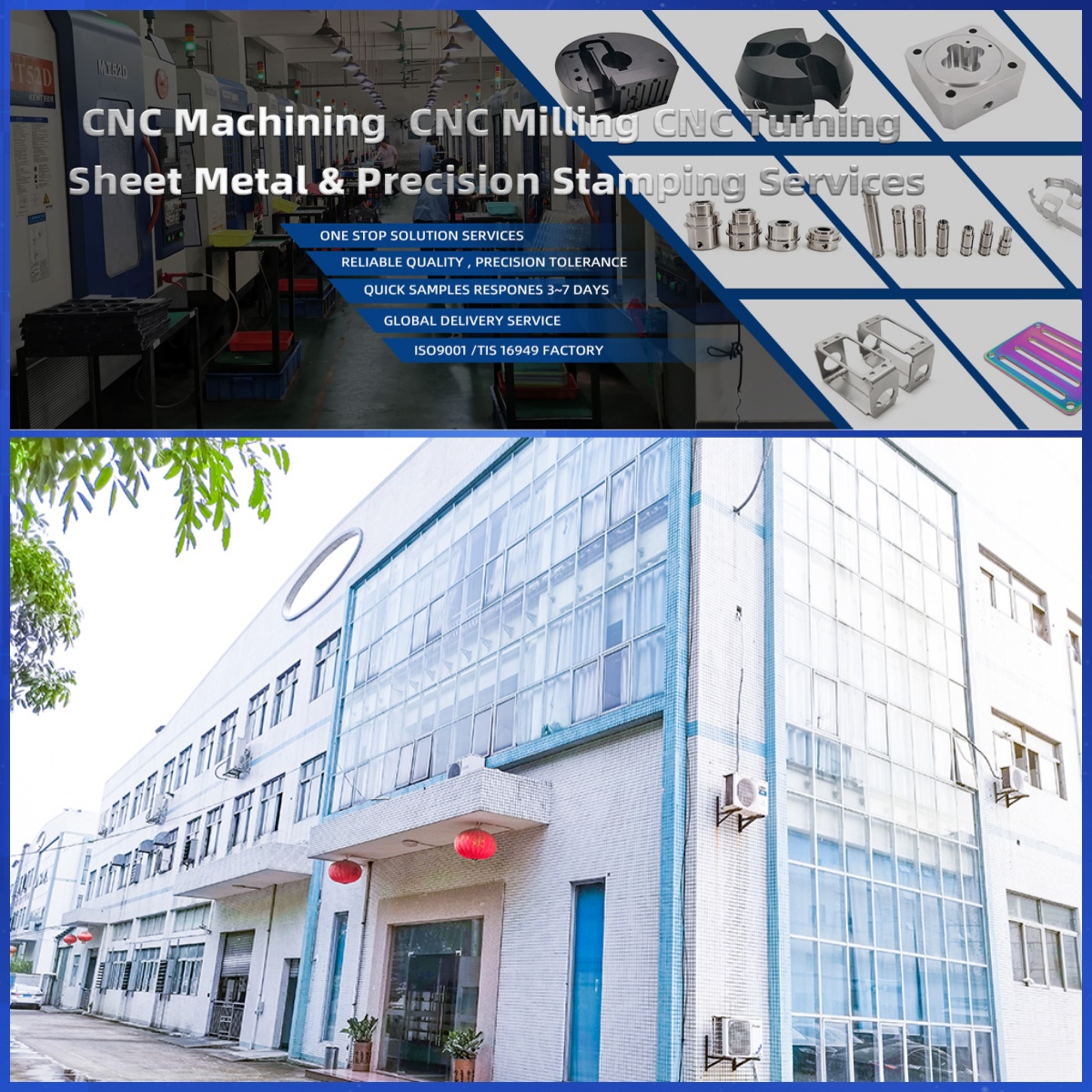
DongGuan YiTai Electronic Technologies Co.,Ltd
DongGuan YiTai Electronic Technologies Co.,Ltd is a manufacturing service provider located in Dongguan, China.
YiTai specialized in CNC turning machining and sheet metal fabrication mainly. As a member of Hung Mou Group, we focus on the overseas marketing development. And based on our parent company’s manufacturing capability and resources, YiTai also expended machining services such as die casting, injection molding, aluminum profile extrusion, 3D printing, which are committed to providing customers with one-stop purchasing services and experience.
CNC MACHINING , CNC MILLING , CNC TURNING , SHEETMETAL , FASTENER , OTHERS


Sheet Metal Deep Drawing: A Complete Guide to the Process, Materials, and Capabilities
Related Article