
7 Steps to Operate A CNC Machining Center
author: YITECH
2024-11-20

CNC machining center is a high-precision machine tool that can perform multiple machining processes in one setup, resulting in increased productivity and accuracy, we are professional on this.
1. Prepare for startup
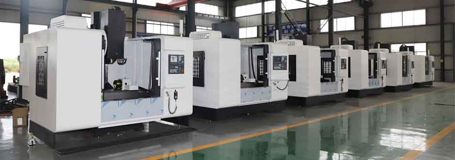
The machine tool is first returned to the reference zero position after each startup or emergency stop of the machine tool, so that the machine tool has a reference position for its subsequent operation. 1. The machine tool is ready for startup. After each startup or the machine tool is reset according to the emergency stop, the machine tool is first returned to the reference zero position, so that the machine tool has a reference position for its future operation.
The machine tool is first returned to the reference zero position after each startup or emergency stop of the machine tool, so that the machine tool has a reference position for its subsequent operation. 1. The machine tool is ready for startup. After each startup or the machine tool is reset according to the emergency stop, the machine tool is first returned to the reference zero position, so that the machine tool has a reference position for its future operation.
2. Clamp the workpiece
Before the workpiece is installed, the surface should be cleaned first, and there should be no oil, iron filings and dust, and the burr on the surface of the workpiece should be removed with a file (or oil stone).
The contour iron used for clamping must be smoothed by the grinder to make the surface smooth and flat. Code iron, nuts must be strong, can reliably clamp the workpiece, some difficult to clamp small workpiece can be directly clamped on the tiger; Machine workbench should be clean, no iron filings, dust, oil; The cushion iron is generally placed at the four corners of the workpiece, and the workpiece with a large span must be placed in the middle of the equal height cushion iron.
According to the dimensions of the drawing, use a drawing rule to check whether the length, width and height of the workpiece are qualified.
When clamping the workpiece, according to the clamping arrangement of the programming work instructions, it is necessary to consider avoiding the machining parts and the situation that the tool head may touch the fixture during processing. After the workpiece is placed on the pad iron, it is necessary to pull the datum surface of the workpiece according to the requirements of the drawing, and check whether the verticality of the workpiece has been ground on six sides.
After the workpiece pulling table is completed, the nut must be tightened to prevent the clamping is not firm and the workpiece is shifted during processing; Pull the watch again to make sure that the error is not out of tolerance after clamping.
Before the workpiece is installed, the surface should be cleaned first, and there should be no oil, iron filings and dust, and the burr on the surface of the workpiece should be removed with a file (or oil stone).
The contour iron used for clamping must be smoothed by the grinder to make the surface smooth and flat. Code iron, nuts must be strong, can reliably clamp the workpiece, some difficult to clamp small workpiece can be directly clamped on the tiger; Machine workbench should be clean, no iron filings, dust, oil; The cushion iron is generally placed at the four corners of the workpiece, and the workpiece with a large span must be placed in the middle of the equal height cushion iron.
According to the dimensions of the drawing, use a drawing rule to check whether the length, width and height of the workpiece are qualified.
When clamping the workpiece, according to the clamping arrangement of the programming work instructions, it is necessary to consider avoiding the machining parts and the situation that the tool head may touch the fixture during processing. After the workpiece is placed on the pad iron, it is necessary to pull the datum surface of the workpiece according to the requirements of the drawing, and check whether the verticality of the workpiece has been ground on six sides.
After the workpiece pulling table is completed, the nut must be tightened to prevent the clamping is not firm and the workpiece is shifted during processing; Pull the watch again to make sure that the error is not out of tolerance after clamping.
3. workpiece touch number
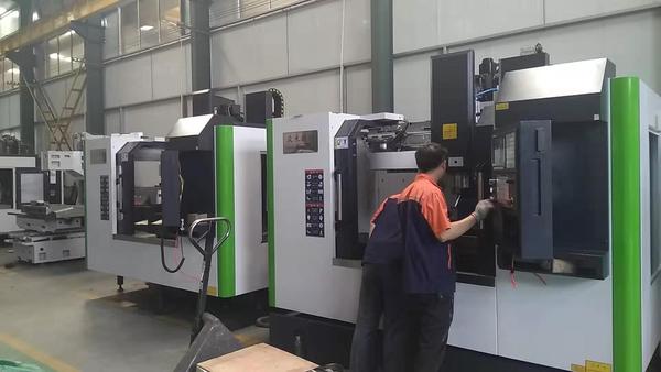
The clamping workpiece can be touched by the touch head to determine the reference zero position, the touch head can be photoelectric and mechanical two kinds. The method is divided into two kinds: middle touch number and single touch number. The steps of middle touch number are as follows:
Photoelectric static, mechanical speed 450~600rpm. Manually move the X-axis of the table to make the head touch one side of the workpiece. When the head touch the workpiece and the red light is on, the relative coordinate value of this point is set to zero; Then manually move the table X axis so that the head touches the other side of the workpiece, and record the relative coordinates when the head just touches the workpiece.
According to its relative value minus the diameter of the contact head (that is, the length of the workpiece), check whether the length of the workpiece meets the requirements of the drawing.
Divide this relative coordinate number by 2, the obtained value is the middle value of the workpiece X axis, and then move the table to the middle value on the X axis, and set the relative coordinate value of the X axis at this point to zero, which is the zero position on the workpiece X axis.
Carefully record the mechanical coordinate value of zero position on the X-axis of the workpiece in one of G54~G59, and let the machine determine the zero position on the X-axis of the workpiece. Check the data carefully again for correctness. The steps for setting the zero position of the Y-axis of the workpiece are the same as those for the X-axis.
The clamping workpiece can be touched by the touch head to determine the reference zero position, the touch head can be photoelectric and mechanical two kinds. The method is divided into two kinds: middle touch number and single touch number. The steps of middle touch number are as follows:
Photoelectric static, mechanical speed 450~600rpm. Manually move the X-axis of the table to make the head touch one side of the workpiece. When the head touch the workpiece and the red light is on, the relative coordinate value of this point is set to zero; Then manually move the table X axis so that the head touches the other side of the workpiece, and record the relative coordinates when the head just touches the workpiece.
According to its relative value minus the diameter of the contact head (that is, the length of the workpiece), check whether the length of the workpiece meets the requirements of the drawing.
Divide this relative coordinate number by 2, the obtained value is the middle value of the workpiece X axis, and then move the table to the middle value on the X axis, and set the relative coordinate value of the X axis at this point to zero, which is the zero position on the workpiece X axis.
Carefully record the mechanical coordinate value of zero position on the X-axis of the workpiece in one of G54~G59, and let the machine determine the zero position on the X-axis of the workpiece. Check the data carefully again for correctness. The steps for setting the zero position of the Y-axis of the workpiece are the same as those for the X-axis.
4. Prepare all the tools according to the programming operation instructions
According to the tool data of the programming work guide, change the tool to be processed, let the tool touch the height measuring device placed on the datum plane, and set the relative coordinate value of this point to zero when the measuring device is red. Move the tool to a safe place, manually move the tool 50mm down, and set the relative coordinate value at this point to zero, which is the zero position of the Z-axis.
Record the mechanical Z value of this point in one of the G54~G59. This completes the zero setting of the X, Y and Z axes of the workpiece. Check the data carefully again for correctness.
Unilateral touch number is also according to the above method to touch the workpiece X, Y axis side, the relative coordinate value of the X, Y axis offset the radius of the head of the touch number is the zero position of the X and Y axis, and finally the mechanical seat of the X and Y axis is marked in one of the G54~G59. Check the data carefully again for correctness.
Check the correctness of the zero point, move the X and Y axes to the edge of the workpiece, and visually check the correctness of the zero point according to the size of the workpiece.
Copy the program file to the computer according to the file path in the programming work guide.
According to the tool data of the programming work guide, change the tool to be processed, let the tool touch the height measuring device placed on the datum plane, and set the relative coordinate value of this point to zero when the measuring device is red. Move the tool to a safe place, manually move the tool 50mm down, and set the relative coordinate value at this point to zero, which is the zero position of the Z-axis.
Record the mechanical Z value of this point in one of the G54~G59. This completes the zero setting of the X, Y and Z axes of the workpiece. Check the data carefully again for correctness.
Unilateral touch number is also according to the above method to touch the workpiece X, Y axis side, the relative coordinate value of the X, Y axis offset the radius of the head of the touch number is the zero position of the X and Y axis, and finally the mechanical seat of the X and Y axis is marked in one of the G54~G59. Check the data carefully again for correctness.
Check the correctness of the zero point, move the X and Y axes to the edge of the workpiece, and visually check the correctness of the zero point according to the size of the workpiece.
Copy the program file to the computer according to the file path in the programming work guide.

5. Setting of processing parameters
Setting of spindle speed in processing:
N=1000 x V/ (3.14 x D)
N: Spindle speed (rpm/min)
V: Cutting speed (m/min)
D: Tool diameter (mm) machining feed speed setting:
F=N×M×FnF: feed speed (mm/min)
M: Cutting edge Fn: cutting amount of the tool (mm/ revolution)
Setting of cutting amount per edge: Fn=Z×Fz
Z: The number of cutting edges of the tool Fz: the cutting amount per cutting edge of the tool (mm/ revolution)
Setting of spindle speed in processing:
N=1000 x V/ (3.14 x D)
N: Spindle speed (rpm/min)
V: Cutting speed (m/min)
D: Tool diameter (mm) machining feed speed setting:
F=N×M×FnF: feed speed (mm/min)
M: Cutting edge Fn: cutting amount of the tool (mm/ revolution)
Setting of cutting amount per edge: Fn=Z×Fz
Z: The number of cutting edges of the tool Fz: the cutting amount per cutting edge of the tool (mm/ revolution)
6. Boot processing
At the beginning of each program execution, it is necessary to carefully check whether the specified tool is being used as stated in the programming guide. When starting processing, the feed speed should be adjusted to the minimum level, executed in single sections. When quickly positioning, lowering the tool, and feeding, it is necessary to concentrate and keep the hand on the stop button to stop immediately if there is a problem. It is important to observe the direction of tool movement to ensure safe feeding. Then gradually increase the feed rate to the appropriate level while adding cooling liquid or air to the tool and workpiece.
When roughing machining, it is not allowed to move too far away from the control panel. If any abnormal phenomena occur, the machine should be stopped immediately for inspection.
After roughing, the machine should be calibrated again to ensure that the workpiece is not loose. If it is loose, re-calibration and homing are necessary.
At the beginning of each program execution, it is necessary to carefully check whether the specified tool is being used as stated in the programming guide. When starting processing, the feed speed should be adjusted to the minimum level, executed in single sections. When quickly positioning, lowering the tool, and feeding, it is necessary to concentrate and keep the hand on the stop button to stop immediately if there is a problem. It is important to observe the direction of tool movement to ensure safe feeding. Then gradually increase the feed rate to the appropriate level while adding cooling liquid or air to the tool and workpiece.
When roughing machining, it is not allowed to move too far away from the control panel. If any abnormal phenomena occur, the machine should be stopped immediately for inspection.
After roughing, the machine should be calibrated again to ensure that the workpiece is not loose. If it is loose, re-calibration and homing are necessary.
In the process of processing, the processing parameters are continuously optimized to achieve the best processing effect.
Because this process is a key process, so after the workpiece is finished processing, it should be measured whether its main size value is consistent with the requirements of the drawing, if there is a problem, immediately notify the shift leader or programmer to check and solve, after passing the self-inspection, it can be removed, and must be sent to the inspector for special inspection.
Machining type: Hole processing: Before drilling in the machining center, it is necessary to use the center drill to locate, and then drill with a drill bit 0.5~2mm smaller than the drawing size, and finally finish with a suitable drill bit.
Reaming processing: For reaming the workpiece, it is also necessary to first locate the center drill, then drill with a drill bit 0.5~0.3mm smaller than the drawing size, and finally reaming with a reamer. During reaming processing, pay attention to controlling the spindle speed within 70~180rpm/min.
Boring processing: the workpiece boring processing should first use the center drill positioning, and then use the drill bit 1~2mm smaller than the drawing size, and then use the rough boring tool (or milling tool) processing to only leave about 0.3mm processing allowance, and finally use the pre-adjusted size of the fine boring tool for fine boring, the last fine boring allowance can not be less than 0.1mm.
Direct numerical control (DNC) operation: Before DNC numerical control machining, it is necessary to install and clamp the workpiece, set the zero position, and set the parameters. Open the processing program to be transferred in the computer to check, and then let the computer enter the DNC state, and enter the file name of the correct processing program. Press the TAPE key and program start key on the machine tool, then the machine tool controller will appear flashing LSK. DNC data transfer processing can be carried out by pressing Enter keyboard on the computer.
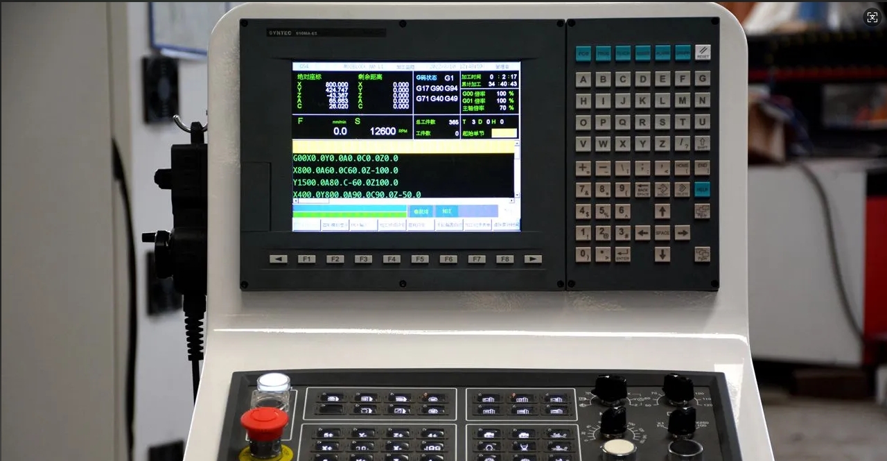
7. The worker self-check content, scope of the processor must see the content of the process card before processing, clearly know the workpiece to be processed parts, shapes, drawing sizes and know its next process processing content.
Before the workpiece is installed, the billet size should be measured to see whether it meets the requirements of the drawing. When the workpiece is installed, it must be carefully checked whether its placement is consistent with the programming operation instruction.
After the roughing is completed, the self-test should be carried out in time to adjust the error data in time. The content of self-test is mainly the position size of the processing part. Such as: whether the workpiece is loose; Whether the workpiece is correctly divided; Whether the size of the machining part to the reference edge (reference point) meets the requirements of the drawing; The position dimensions of the machining parts in relation to each other. After checking the position dimensions, the roughed shape ruler should be measured (except for the arc).
After the roughing self-inspection, the finishing is carried out. After finishing, workers should self-check the shape and size of the processing parts: detect the basic length and width of the processing parts in the vertical plane; Measure the base point dimensions marked on the drawing for the machining part of the bevel.
After the worker completes the workpiece self-inspection and confirms that it conforms to the drawing and process requirements, the workpiece can be removed and sent to the inspector for special inspection.
Before the workpiece is installed, the billet size should be measured to see whether it meets the requirements of the drawing. When the workpiece is installed, it must be carefully checked whether its placement is consistent with the programming operation instruction.
After the roughing is completed, the self-test should be carried out in time to adjust the error data in time. The content of self-test is mainly the position size of the processing part. Such as: whether the workpiece is loose; Whether the workpiece is correctly divided; Whether the size of the machining part to the reference edge (reference point) meets the requirements of the drawing; The position dimensions of the machining parts in relation to each other. After checking the position dimensions, the roughed shape ruler should be measured (except for the arc).
After the roughing self-inspection, the finishing is carried out. After finishing, workers should self-check the shape and size of the processing parts: detect the basic length and width of the processing parts in the vertical plane; Measure the base point dimensions marked on the drawing for the machining part of the bevel.
After the worker completes the workpiece self-inspection and confirms that it conforms to the drawing and process requirements, the workpiece can be removed and sent to the inspector for special inspection.
If you need cnc machining center service, please feel free to contact us!
Four Types of Profiles
Ways of powder coating
Related Article

Choosing between 316 and 316L? 316L resists weld decay better, 316 holds strength at higher heat. Both food-grade, both marine-grade. Quick, no-fluff breakdown.
316 vs 316L Stainless Steel for CNC Machining
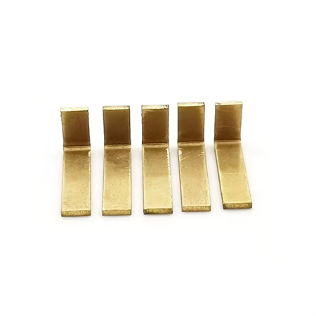
What is stamping and when do you use it? A plain guide to sheet metal stamping, dies, and progressive tools, plus the parts it makes faster than machining.
What Is Stamping in Metal Manufacturing?

